
AEC Insights
From Requirements to Reliable Data
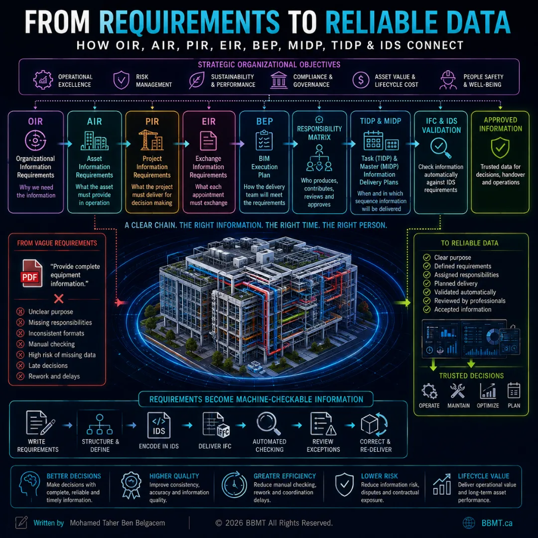
Reliable BIM information does not begin with adding parameters to a model. It begins when an organization identifies the decisions it must make, converts those needs into clear exchange requirements, assigns delivery responsibilities, plans each information milestone, and validates the final IFC data against measurable rules.
From Requirements to Reliable Data
How OIR, AIR, PIR, EIR, BEP, Responsibility Matrices, MIDP, TIDP, and IDS Connect
A project team may produce visually impressive models containing thousands of objects and millions of data points.
That does not necessarily mean the information is useful.
A model can be geometrically complete while still failing to answer basic questions:
Which equipment requires maintenance?
Who manufactured it?
What is its warranty period?
Which system does it serve?
When must the information be delivered?
Who is responsible for creating it?
Which values are mandatory?
How will the receiving party verify them?
What happens when the delivered information is incomplete?
These failures rarely begin inside the modeling software.
They usually begin much earlier, when the project’s information needs are vague, disconnected, contradictory, or never formally defined.
ISO 19650 establishes a framework for managing information across the lifecycle of built assets, including its exchange, recording, versioning, organization, delivery, and use. Its principles apply from strategic planning and project delivery through operation, maintenance, refurbishment, and end of life.
The framework creates a chain between organizational decisions and delivered information:
Organizational objectives
↓
Organizational Information Requirements
↓
Asset and Project Information Requirements
↓
Exchange Information Requirements
↓
BIM Execution Plan and delivery responsibilities
↓
Task and Master Information Delivery Plans
↓
Information production
↓
Validation and acceptance
When that chain is complete, information has a defined purpose, owner, format, delivery date, and acceptance method.
When the chain is broken, teams frequently produce too much information, too little information, or the wrong information at the wrong time.
1. Information Requirements Are the Starting Point
Information requirements explain what information is needed, why it is needed, when it must be delivered, who will receive it, and how its suitability will be assessed.
They should not begin with a list of software parameters.
They should begin with a decision.
For example:
The asset owner needs to reduce unplanned mechanical-equipment downtime.
That objective creates questions:
Which equipment is operationally critical?
Where is it installed?
Who manufactured it?
What is its model number?
What maintenance does it require?
Which spare parts are needed?
When does its warranty expire?
Which systems and spaces depend on it?
Only after those questions are understood should the organization determine which model properties, documents, classifications, identifiers, and relationships must be delivered.
The UK BIM Framework guidance describes information requirements as the inputs to the wider information-management ecosystem and identifies four connected requirement resources: OIR, AIR, PIR, and EIR. It also emphasizes that requirements should be structured consistently so that information delivery—and where suitable, automated verification—can be performed effectively.
The guiding principle is:
Purpose first. Information second. Technology third.
2. Understanding the Parties
ISO 19650 uses specific terms for the organizations participating in an appointment.
Appointing Party
The appointing party is the organization receiving information and appointing another party to provide it.
Depending on the project, this may be:
The client
The owner
The developer
The asset operator
A general contractor appointing a subcontractor
A lead consultant appointing a specialist
Lead Appointed Party
The lead appointed party manages a delivery team for a particular appointment.
This may be:
The prime consultant
The general contractor
A design-build organization
A major trade contractor
A facilities-management provider
Appointed Party
An appointed party performs tasks and produces information within the delivery team.
Examples include:
Architect
Structural engineer
MEP consultant
Fabricator
Surveyor
Specialist subcontractor
Commissioning provider
The same organization may occupy different positions under different appointments.
The important distinction is between:
The party requiring and receiving information
The party coordinating its delivery
The parties producing it
3. OIR: Organizational Information Requirements
Organizational Information Requirements, or OIR, describe the strategic information an organization needs to achieve its objectives and make informed decisions.
OIR should originate from matters such as:
Business strategy
Portfolio management
Regulatory obligations
Risk management
Sustainability targets
Financial reporting
Health and safety
Operational performance
Capital planning
Corporate governance
Examples of organizational objectives include:
Reduce portfolio energy consumption by 20 percent
Improve space utilization
Reduce unplanned equipment downtime
Standardize lifecycle-cost reporting
Improve regulatory compliance
Compare asset performance across multiple facilities
Reduce maintenance expenditure
Support future acquisition or disposal decisions
The OIR does not normally describe every model property.
It explains the strategic questions the organization must be able to answer.
Example OIR
The organization must be able to compare the reliability, maintenance cost, energy consumption, and replacement risk of mechanical equipment across its entire property portfolio.
This requirement may eventually lead to the collection of:
Equipment identifiers
Asset locations
Manufacturers
Model numbers
Installation dates
Expected service lives
Maintenance histories
Energy-performance data
Failure records
Replacement costs
However, those detailed fields are downstream consequences of the organizational requirement—not the OIR itself.
OIR sit at the top of the information-requirement hierarchy and contribute to both asset and project information requirements.
4. AIR: Asset Information Requirements
Asset Information Requirements, or AIR, define the information needed to operate, maintain, monitor, manage, modify, or dispose of an asset.
They translate organizational objectives into asset-related information needs.
AIR may support:
Preventive maintenance
Reactive maintenance
Condition assessment
Energy management
Space management
Compliance inspections
Warranty management
Spare-parts planning
Lifecycle costing
Emergency response
Refurbishment
Decommissioning
Example
An organization’s OIR may state:
Reduce operational downtime and improve maintenance planning.
The corresponding AIR may require maintainable equipment to include:
Unique asset identifier
Asset type
Description
Manufacturer
Model reference
Serial number
Installation date
Warranty start and end dates
Expected service life
Criticality classification
Maintenance interval
System assignment
Building, storey, and space location
Operations and maintenance documentation
AIR should focus on information that will actually be used.
Collecting data merely because a software application can store it creates unnecessary work and makes important information harder to find.
AIR and the Asset Information Model
The required operational information is ultimately organized within the Asset Information Model, or AIM.
The AIM is not necessarily one three-dimensional model. It may combine:
IFC models
Asset registers
Documents
Maintenance records
Databases
Photographs
Sensor references
Classification data
Geographic information
Links to operational systems
ISO 19650-3 addresses information management during the operational phase and the exchanges required to maintain usable asset information.
5. PIR: Project Information Requirements
Project Information Requirements, or PIR, define the high-level information needed to make decisions about a particular project.
They may be influenced by:
The organizational objectives
Project business case
Strategic brief
Project governance
Funding approvals
Design decisions
Regulatory approvals
Procurement strategy
Cost and schedule control
Construction planning
Handover objectives
PIR are project-specific.
They help answer questions such as:
Is the proposed project financially viable?
Does the design satisfy the brief?
Is the project progressing within budget?
Can the design be constructed safely?
Are planning and regulatory approvals achievable?
Are the project’s sustainability targets being met?
Is sufficient information available to begin procurement?
Is the facility ready for handover and operation?
Example PIR
The project must provide sufficient information at each approval milestone to verify capital cost, operational energy performance, maintainability, construction risk, and compliance with the owner’s design standards.
The resulting information may include:
Areas and capacities
Cost plans
Energy simulations
Design-risk information
Equipment schedules
Access and maintenance clearances
Construction sequencing
Regulatory submission documents
Commissioning status
Handover readiness
AIR and PIR are both derived from strategic organizational needs, but they serve different perspectives:
AIR PIR Focuses on the asset’s operational life Focuses on project decisions and delivery Supports maintenance and asset management Supports planning, design, procurement, and construction Continues throughout operation Primarily drives project-delivery information Contributes to the AIM Contributes to the Project Information Model
The UK BIM Framework presents AIR and PIR as high-level requirements derived from OIR. Together, they provide the inputs from which appointment-specific Exchange Information Requirements are developed.
6. EIR: Exchange Information Requirements
Exchange Information Requirements, or EIR, specify the information required from a particular appointed party at defined information exchanges.
Under ISO 19650, EIR means:
Exchange Information Requirements
It should not be confused with the older expression Employer’s Information Requirements, which appeared frequently in pre-ISO UK BIM terminology.
The EIR converts high-level needs into an appointment-specific instruction.
It should make clear:
Why the information is needed
What information must be delivered
Who will provide it
Who will receive it
When it must be exchanged
What information containers are expected
What form and format must be used
What classification or data structure applies
What level of information need is required
Which acceptance criteria will be applied
How the delivery will be reviewed and authorized
UK BIM Framework guidance describes EIR as the appointing party’s requirements for a particular exchange with a specific lead appointed party, including the information purpose, required content, format, and level of information need.
One Project Can Have Multiple EIR
A project does not necessarily have one universal EIR document.
Different appointments may require different exchanges.
For example:
The architect may receive EIR for planning, spatial, and envelope information.
The structural engineer may receive EIR for analysis, coordination, and fabrication interfaces.
The mechanical contractor may receive EIR for equipment, systems, clearances, and commissioning.
The general contractor may issue EIR to fabricators for production and installation information.
The asset operator may require operational information at handover.
Each EIR should be proportionate to the appointment.
Example EIR
At the coordinated-design milestone, the mechanical lead appointed party must deliver:
One validated IFC4 reference model
Mechanical systems separated by system type
Equipment classified using the project classification system
Maintainable equipment assigned to the correct building storey and space
Manufacturer and model information where products have been selected
Required flow rate and power properties
Maintenance-access zones
One equipment schedule in XLSX format
A validation report
A list of unresolved exceptions
The EIR should also define:
Exchange date
File naming
Coordinate system
IFC configuration
Required properties
Permitted units
Acceptance criteria
Responsible reviewer
Status and revision requirements
This is much more useful than writing:
“Provide a coordinated BIM model at LOD 300.”
7. The Complete Requirements Hierarchy
The requirement hierarchy can be summarized as follows:
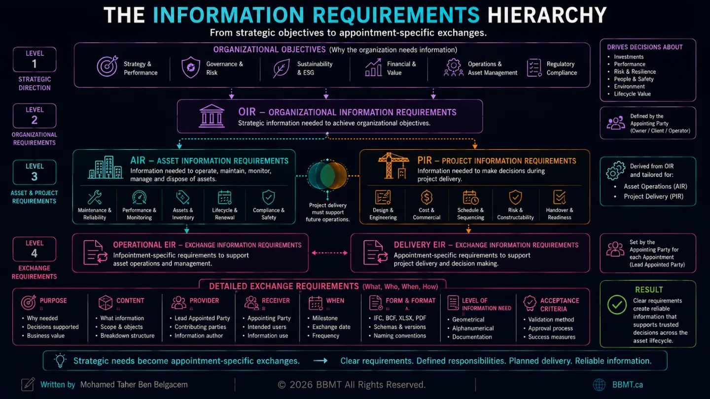
OIR — Why the Organization Needs Information
We need to reduce maintenance cost and operational risk.
AIR — What the Asset Team Needs
We need structured information about maintainable equipment, its condition, location, expected life, and maintenance requirements.
PIR — What the Project Must Demonstrate
The project must demonstrate that the selected systems are maintainable, cost-effective, coordinated, and ready for operational handover.
EIR — What a Specific Party Must Deliver
At the handover milestone, provide each maintainable mechanical asset with a unique identifier, classification, manufacturer, model, warranty data, system assignment, verified location, maintenance documentation, and acceptance status.
The hierarchy prevents detailed requirements from becoming disconnected from their original purpose.
Every required property should be traceable back to a decision or operational need.
A useful test is:
Which decision becomes impossible or less reliable if this information is missing?
When no clear answer exists, the requirement may not be necessary.
8. Level of Information Need: How Much Is Enough?
After defining what information is needed, the project must define the appropriate extent and detail.
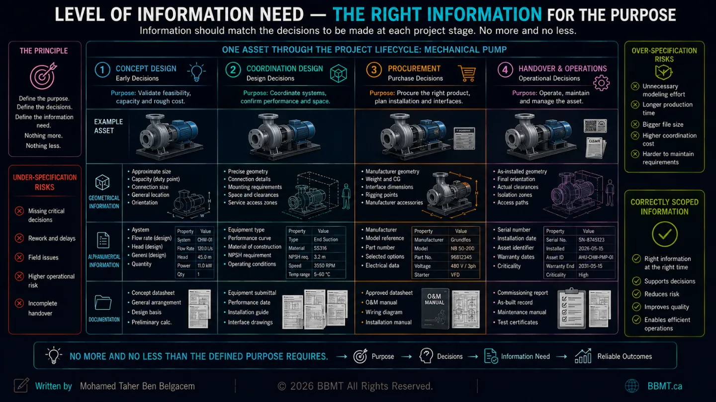
This is the purpose of the level of information need.
ISO 7817-1:2024 provides concepts and principles for specifying the detail and extent of information required in a consistent way throughout the built-asset lifecycle.
The level of information need can address:
Geometrical Information
Quantity
Size
Shape
Location
Orientation
Representation
Required accuracy
Alphanumerical Information
Object names
Classifications
Properties
Values
Units
Identifiers
Status information
Documentation
Specifications
Calculations
Certificates
Reports
Photographs
Manuals
Test records
Prerequisites
The requirement should also establish:
Purpose
Information-delivery milestone
Information provider
Information receiver
Relevant objects
Breakdown structure
The level of information need should not be treated as a request for maximum detail.
Its purpose is to establish:
The right information, in the right amount, for the defined purpose.
Over-specification increases modeling effort, file size, checking time, and contractual exposure.
Under-specification leaves teams unable to make reliable decisions.
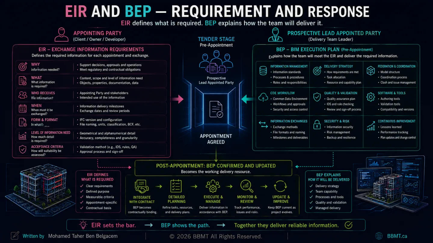
9. The BEP: How the Delivery Team Will Respond
The BIM Execution Plan, or BEP, explains how the prospective or appointed delivery team intends to manage and deliver information in response to the appointing party’s requirements.
The EIR asks:
What must be delivered?
The BEP responds:
How will we deliver it?
Pre-Appointment BEP
During tendering, the prospective lead appointed party prepares a pre-appointment BEP.
Its purpose is to demonstrate that the proposed delivery team:
Understands the EIR
Has an appropriate information-management approach
Has sufficient capability and capacity
Can organize the delivery team
Can meet the required milestones
Can manage the proposed exchange formats
Has considered coordination, federation, quality, and risk
UK BIM Framework guidance describes the pre-appointment BEP as evidence that the prospective delivery team can manage information in line with the requirements issued by the appointing party.
Delivery Team’s BEP
After appointment, the BEP is reviewed, confirmed, and updated.
It becomes one of the delivery team’s working information-management resources.
It may define:
Information-management functions
Team structure
Standards and procedures
Naming conventions
CDE workflow
Model federation strategy
Coordination process
Software and exchange formats
Quality assurance
Review and approval
Issue management
Security
Change management
Delivery planning
The BEP must not replace the EIR.
A delivery team cannot respond meaningfully to requirements that were never clearly defined.
The formal sequence is:
Appointing party defines EIR
↓
Prospective delivery team prepares pre-appointment BEP
↓
Appointment is agreed
↓
BEP is confirmed and updated
↓
Responsibilities and delivery plans are finalized
The BEP should remain current as appointments, team members, systems, and project conditions change.
10. Responsibility Matrices: Connecting Information to People
Requirements identify what is needed.
A responsibility matrix identifies who must produce, contribute to, review, or authorize it.
A useful responsibility matrix connects at least three fundamental questions:
What information must be produced?
Who is responsible for producing it?
When must it be exchanged?
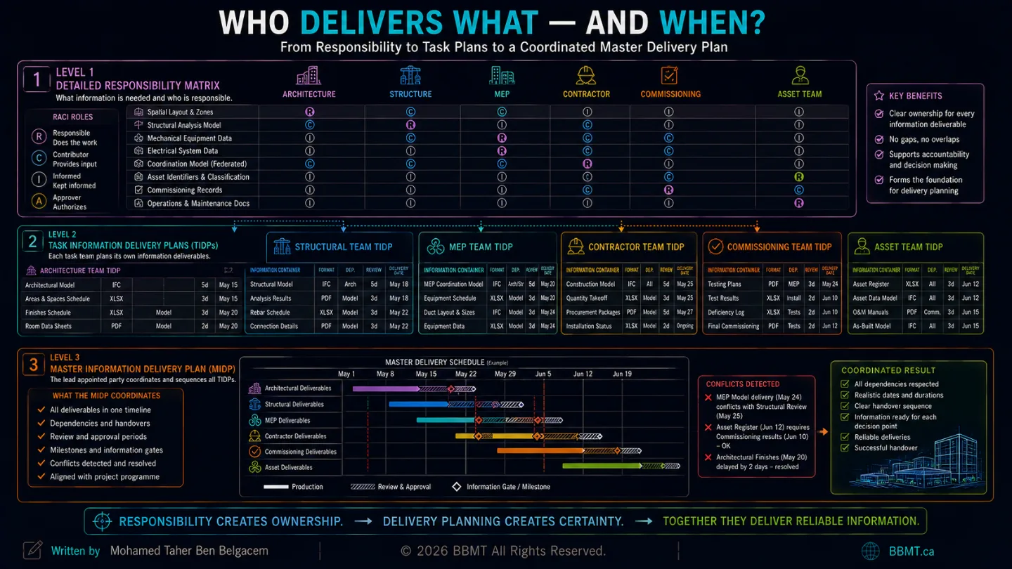
High-Level Responsibility Matrix
The high-level responsibility matrix is developed during the tender and pre-appointment stage.
It may assign broad responsibilities for:
Architectural information
Structural information
Mechanical systems
Electrical systems
Civil works
Cost information
Construction planning
Asset information
Health and safety information
It helps demonstrate that the proposed team has understood the overall scope.
Detailed Responsibility Matrix
After appointment, the matrix is refined.
Instead of assigning “Mechanical Model” to one party, it may identify:
Equipment geometry
System classification
Design flow rates
Manufacturer information
Maintenance clearances
Electrical requirements
Installation status
Commissioning results
Asset identifiers
Operations documentation
Different parties may contribute to the same object at different stages.
For example:
Information Responsible party Design performance Mechanical engineer Spatial location Mechanical designer Manufacturer and model Mechanical contractor Electrical connection Electrical contractor Installation status Site team Commissioning result Commissioning authority Asset identifier Owner or asset-information team Final acceptance Appointing party
The UK BIM Framework describes a progressive process in which a high-level responsibility matrix is developed before appointment, then refined into a detailed matrix that informs the task and master information-delivery plans.
Responsibility Matrix vs. Assignment Matrix
These should not be confused.
A responsibility matrix assigns delivery-team responsibilities for information tasks and deliverables.
An information-management assignment matrix assigns responsibility for performing the information-management activities described by the standard.
They serve different purposes.
11. TIDP: Task Information Delivery Plan
A Task Information Delivery Plan, or TIDP, is prepared by each task team.
It identifies the information containers that the task team is responsible for delivering.
A task team may represent:
Architecture
Structure
Mechanical systems
Electrical systems
Civil works
Cost planning
Fabrication
Commissioning
Asset information
A TIDP should typically identify:
Information container name
Description
Originator
Responsible task team
Required format
Required level of information need
Estimated production duration
Internal review duration
Planned delivery date
Information-delivery milestone
Dependencies
Required inputs
Status
Example Mechanical TIDP
Deliverable Format Responsible team Milestone Mechanical coordination model IFC Mechanical design Coordination Gate 2 Equipment schedule XLSX Mechanical design Coordination Gate 2 Maintenance-clearance model IFC Mechanical design Coordination Gate 3 Manufacturer data IFC/XLSX Mechanical contractor Procurement release Commissioning records PDF/XLSX Commissioning team Handover Final asset register IFC/XLSX Asset-information team Handover
The TIDP translates responsibility into scheduled production.
It is where “we will provide the information” becomes:
This task team will deliver this specific information container, in this format, on this date, for this milestone.
12. MIDP: Master Information Delivery Plan
The Master Information Delivery Plan, or MIDP, consolidates and coordinates the TIDPs prepared by the task teams within a delivery team.
The lead appointed party is responsible for coordinating the task-team plans and compiling them into the MIDP.
The MIDP provides a coordinated view of:
All planned information deliverables
Responsible task teams
Exchange dates
Project milestones
Dependencies
Review periods
Approval activities
Required formats
Information sequencing
Why Consolidation Matters
Individual TIDPs may appear reasonable when reviewed separately while still conflicting with one another.
For example:
The architect plans to issue ceiling information on June 15.
The mechanical team plans to finalize ductwork on June 1.
The electrical team requires coordinated ceiling zones by May 20.
The coordination review is scheduled for May 25.
The dates are individually documented but collectively impossible.
The MIDP exposes these dependencies so that information delivery can be coordinated with the project programme.
The relationship is:
Each task team creates a TIDP
↓
The lead appointed party coordinates the TIDPs
↓
The coordinated plans become the MIDP
The MIDP is not merely a list of files.
It is the delivery team’s information-production programme.
13. From a Written Requirement to a Model Property
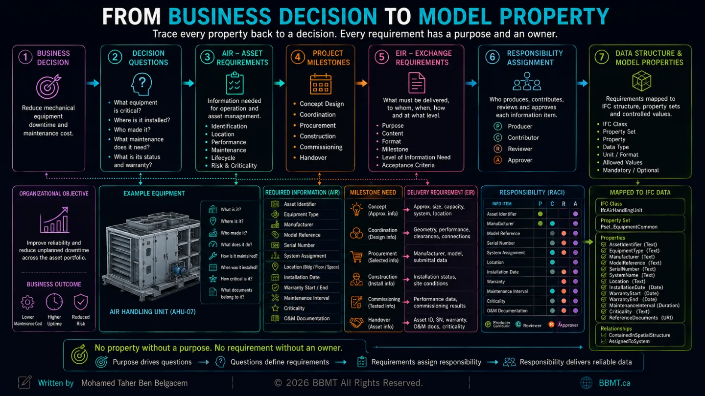
A frequent failure occurs when requirements remain inside long PDF documents that modelers never translate into production rules.
A written requirement must pass through several stages before it becomes reliable model data.
Step 1: Define the Purpose
The operator must identify equipment affected by a manufacturer recall.
Step 2: Identify the Relevant Objects
All maintainable mechanical equipment.
Step 3: Define the Required Information
Manufacturer
Model reference
Serial number
Asset identifier
Installation location
Step 4: Define the Data Structure
IFC class
Property set
Property name
Data type
Unit
Classification system
Permitted values
Naming rule
Step 5: Define the Information Milestone
Manufacturer and model information required at procurement release; serial number required at handover.
Step 6: Assign Responsibility
Designer specifies performance
Contractor identifies selected product
Installer records serial number
Commissioning team verifies installation
Asset team approves final record
Step 7: Define the Delivery Container
IFC model
Asset-register spreadsheet
Product-data sheet
Commissioning record
Step 8: Define the Acceptance Rule
Property must exist
Value cannot be blank
Value must use the required format
Equipment must have a valid classification
Equipment must belong to a system
Equipment must be assigned to the appropriate spatial location
Only after these decisions are made can the model template, shared parameters, export mapping, spreadsheet, database, or IFC property structure be configured correctly.
14. IDS: Making Requirements Machine-Readable
Many information requirements are still communicated through:
PDF documents
Word files
Spreadsheets
Email instructions
Meeting minutes
These formats may be readable by people, but they are difficult for software to interpret consistently.
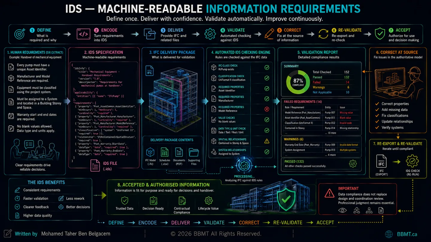
Information Delivery Specification, or IDS, provides a standardized method for expressing selected IFC information requirements in a computer-interpretable form.
buildingSMART approved IDS 1.0 as a final standard in June 2024. IDS can define information requirements in a form that is readable by people and processable by software, enabling automatic compliance checking of IFC deliveries.
IDS can specify requirements involving:
IFC objects and classes
Attributes
Classifications
Materials
Properties
Required values
Permitted values
Data patterns
Cardinality
Relevant object relationships
Example Human-Readable Requirement
Every pump included in the handover model must be classified correctly and must include a manufacturer, model reference, asset identifier, and building-storey assignment.
Equivalent IDS Logic
Applicability
Object is an IfcPump
Object is included in the handover IFC
Requirements
Manufacturer is required
Model reference is required
Asset identifier is required
Classification is required
Storey containment is required
Blank values are not permitted
A compatible IDS checker can then identify:
Passing pumps
Missing properties
Invalid values
Incorrect classifications
Missing containment
Noncompliant objects
15. What IDS Does Not Replace
IDS is powerful, but it is not the entire information-management process.
It does not replace:
OIR
AIR
PIR
The complete EIR
BEP
Responsibility matrices
TIDP
MIDP
Human coordination
Design review
Geometric verification
Contractual acceptance
Professional judgment
IDS is closely tied to IFC and machine-checkable information requirements. buildingSMART describes it as a lightweight standardized approach for specifying and checking what data should be included in an IFC dataset.
Some requirements may remain outside IDS, including:
Whether a design solves the client’s operational problem
Whether equipment is accessible for replacement
Whether a drawing communicates construction intent clearly
Whether the proposed sequence is safe
Whether a model is coordinated constructibly
Whether a document has been professionally approved
Whether the information is suitable for contractual reliance
IDS validates defined data conditions.
It does not automatically validate the quality of the underlying design.
16. The Automated IFC Validation Workflow
A controlled validation workflow may follow this sequence:
1. Define Requirements
OIR, AIR, and PIR establish why information is needed.
2. Prepare EIR
The appointing party defines the appointment-specific exchange.
3. Create IDS
Machine-checkable IFC requirements are encoded in IDS.
4. Prepare the BEP
The delivery team explains how the requirements will be satisfied.
5. Assign Responsibilities
The responsibility matrix defines who creates, contributes to, checks, and approves each information item.
6. Plan Delivery
TIDPs and the MIDP define the containers, milestones, and dates.
7. Produce Information
Task teams model, classify, document, and review the required information.
8. Export IFC
The approved export configuration is applied.
9. Run Automated Validation
The IFC is checked against IDS.
10. Review Exceptions
Failures are assessed to determine whether they are:
Actual missing information
Incorrect values
Incorrect mappings
Export problems
Approved exceptions
Incorrect validation rules
11. Correct at the Source
The responsible team corrects the original model or data source.
12. Re-Export and Revalidate
A revised IFC is generated and checked again.
13. Perform Human Review
The team reviews:
Geometry
Coordination
Constructability
Documentation
Information context
Professional suitability
14. Accept or Reject the Exchange
The appointing party or delegated reviewer determines whether the delivery is acceptable for its defined purpose.
Automated checking should reduce repetitive inspection.
It should not remove accountable human approval.
17. A Complete Worked Example
Organizational Objective
Reduce the cost and duration of mechanical-equipment failures.
OIR
The organization must be able to compare equipment reliability, failure history, maintenance requirements, and replacement risk across its portfolio.
AIR
Each maintainable mechanical asset must include:
Unique asset identifier
Equipment type
Manufacturer
Model reference
Serial number
System
Location
Installation date
Warranty information
Maintenance interval
Expected service life
Criticality
Operations documentation
PIR
The project must demonstrate that mechanical equipment is:
Maintainable
Accessible
Correctly selected
Coordinated
Commissioned
Ready for operational handover
EIR
At the handover milestone, the mechanical delivery team must provide:
Validated IFC model
Final equipment schedule
Asset-register data
Product documentation
Commissioning records
Required classifications and properties
Verified spatial and system assignments
Validation report
BEP Response
The lead appointed party proposes:
Approved IFC schema
Property-mapping method
Classification standard
Model-authoring responsibilities
CDE workflow
Coordination and validation procedures
Data-review process
Approved software and checking tools
Correction and resubmission process
Responsibility Matrix
Information Producer Verifier Equipment performance Mechanical engineer Design lead Manufacturer and model Mechanical contractor Mechanical engineer Serial number Installer Commissioning team System assignment Mechanical designer BIM coordinator Spatial location Mechanical designer BIM coordinator Asset identifier Asset-information team Owner Commissioning status Commissioning provider Owner representative
TIDPs
Each task team identifies the information containers it will deliver and the relevant dates.
MIDP
The lead appointed party coordinates the task plans into one delivery programme.
IDS
The IDS checks that every applicable equipment object contains the required IFC class, classification, properties, values, and relationships.
Final Review
The automated report verifies data compliance.
The project team separately reviews geometry, access, coordination, documentation, and operational suitability.
This is how a strategic business objective becomes structured, validated asset information.
18. Common Failures
Starting With Parameters
The team creates hundreds of parameters without first defining the decisions they support.
Copying Generic EIR Templates
The appointing party issues requirements copied from another project without adapting them to its assets, appointments, or intended uses.
Treating the BEP as the Requirement
The delivery team is asked to define both what the client needs and how it will be delivered, creating unclear accountability.
Using One Responsibility per Object
Responsibility is assigned to one discipline even though information about the object is produced by several parties over time.
Creating TIDPs Without Dependencies
Task teams schedule their own outputs without considering the information they require from others.
Treating the MIDP as a Static File Register
The plan lists deliverables but does not coordinate review durations, dependencies, milestones, or changes.
Requiring Maximum Information at Every Stage
Detailed fabrication or asset data is requested before products and suppliers have been selected.
Encoding Unclear Requirements in IDS
Automation makes a bad requirement fail faster; it does not make the requirement correct.
Accepting an IFC Because It Passed IDS
The data may comply while the geometry, design, coordination, or intended use remains unacceptable.
19. Implementation Checklist
Before launching the information-delivery process, confirm the following.
Strategic Requirements
Organizational objectives are documented.
Information supports identifiable decisions.
Regulatory and operational needs are included.
Unnecessary information has been removed.
Asset and Project Requirements
AIR support actual operational workflows.
PIR support project decisions and milestones.
Project and operational requirements are aligned.
Required information is proportionate to its purpose.
Exchange Requirements
EIR are appointment-specific.
Purposes and milestones are clear.
Information receivers and providers are identified.
Form, format, classification, and units are defined.
Acceptance criteria are measurable.
Level of information need is specified.
Delivery Response
The BEP responds directly to the EIR.
Information-management functions are assigned.
Production methods are documented.
CDE and exchange workflows are defined.
Quality and validation procedures are agreed.
Responsibility and Planning
High-level and detailed responsibility matrices exist.
Every deliverable has a responsible task team.
Each task team has a TIDP.
TIDPs identify dependencies and review durations.
The TIDPs are coordinated into the MIDP.
Plans are updated through change control.
Data and Validation
Written requirements are mapped to data structures.
IFC classes and properties are defined.
IDS is used where requirements are machine-checkable.
Validation tools and versions are agreed.
Exceptions have a controlled approval process.
Corrections are made in authoritative source information.
Human review follows automated checking.
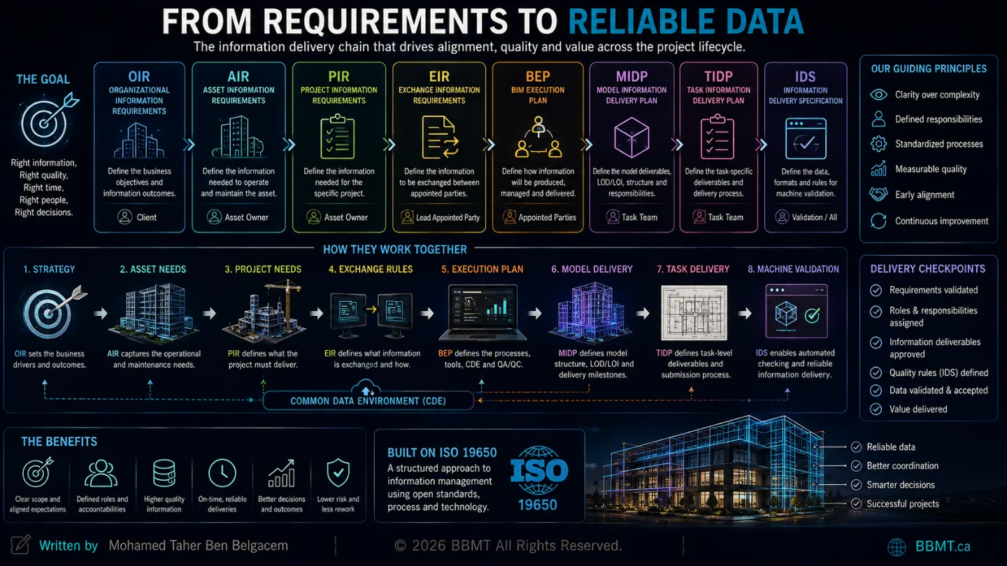
Conclusion: Requirements Create Reliability
Reliable information does not appear automatically because a project uses BIM, IFC, a CDE, or advanced validation software.
Reliability is created through a connected chain.
The organization defines what it needs to achieve.
OIR translate those objectives into strategic information needs.
AIR define the information required to operate the asset.
PIR define the information needed to deliver and govern the project.
EIR specify what must be exchanged under each appointment.
The BEP explains how the delivery team will satisfy those requirements.
Responsibility matrices establish who will produce and verify the information.
TIDPs plan the work of each task team.
The MIDP coordinates the delivery of the entire team.
IDS converts suitable IFC requirements into machine-readable validation rules.
Automated checking confirms whether the required data has been delivered.
Professional review determines whether that information is correct, coordinated, and fit for purpose.
The process should never begin with:
“Which properties can we add to the model?”
It should begin with:
“Which decisions must this information support?”
Reliable information does not begin with modeling. It begins with a clearly defined requirement.