

BIM Coordination
The Pillars of Model Integrity
OpenBIM, IFC and Model Integrity Reliable BIM coordination depends on more than visually accurate models. This chapter explains how openBIM and IFC enable software interoperability, how georeferencing keeps every discipline aligned in the same physical location, and how Level of Development and information requirements define exactly what project teams can trust.

Chapter 4: The Pillars of Model Integrity
openBIM, IFC, Georeferencing, and Level of Development
In the previous chapters, we established the collaborative mindset, governance documents, and coordination processes that support a successful BIM project.
However, even the best coordination process will fail when the underlying models cannot be trusted.
When architectural, structural, mechanical, electrical, plumbing, civil, and fabrication models are brought together, the project team must answer three essential questions:
Can the different software platforms exchange information reliably?
Will every model appear in the correct physical location?
Is each model element sufficiently developed for its intended use?
These questions form the three technical pillars of model integrity:
A unified language: openBIM and IFC
A unified space: georeferencing and common coordinates
Unified expectations: Level of Development and information requirements
Together, these pillars transform a collection of disconnected models into a coordinated information system that project participants can understand, verify, and rely on.
1. The Unified Language: openBIM and IFC
Modern projects rarely operate within a single software ecosystem.
The architect may use one authoring platform, the structural engineer another, and the mechanical team a specialized system designed for analysis or fabrication. Contractors, manufacturers, owners, and facility managers may use completely different tools.
Attempting to exchange only proprietary native files creates several risks:
Software-version incompatibility
Limited access for participants without the original application
Loss of control over long-term information accessibility
Dependence on a single vendor
Unclear exchange responsibilities
Difficulty validating information consistently
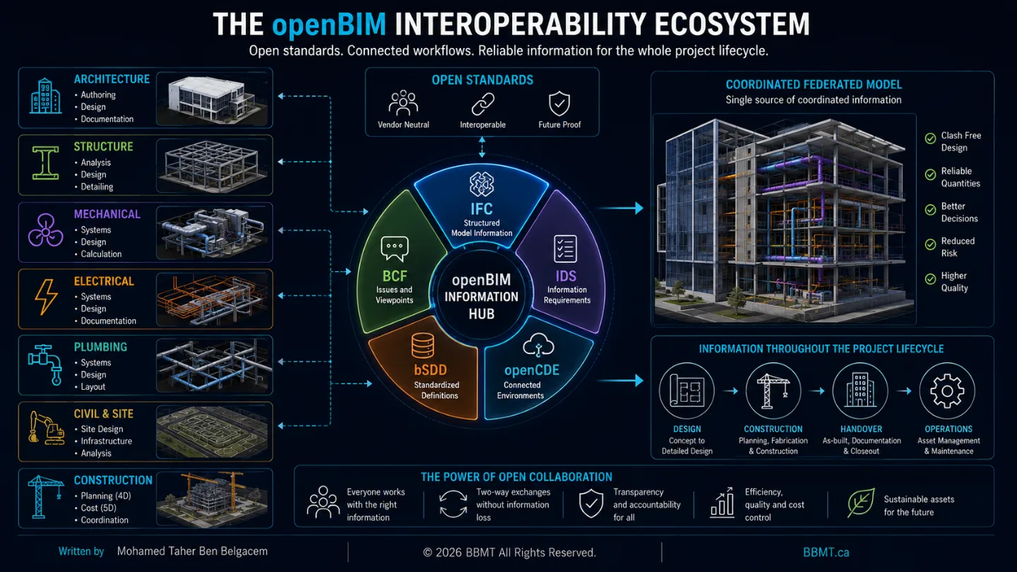
openBIM addresses this challenge by supporting vendor-neutral information exchange and collaboration across software platforms and project participants.
The openBIM ecosystem includes standards and services such as:
IFC for structured asset and model information
BCF for coordination issues and viewpoints
IDS for machine-readable information requirements
bSDD for standardized terminology and data definitions
openCDE interfaces for connected information environments
openBIM is therefore not a single file format or software product. It is a collaborative approach based on open standards, transparent information requirements, and controlled exchanges.
IFC Is More Than a 3D File
The backbone of openBIM model exchange is IFC, or Industry Foundation Classes.
IFC is sometimes described as the “PDF of BIM.” This metaphor is useful because IFC enables information to be viewed independently from its original authoring application.
However, IFC is much more sophisticated than a PDF.
It is an open, standardized information schema that defines how built-asset information can be structured, related, exchanged, and interpreted by software applications.
The current international standard is ISO 16739-1:2024. It covers information used for buildings and infrastructure throughout their life cycles, including roads, bridges, railways, waterways, and port facilities.
An IFC exchange may contain:
Project and site information
Buildings, storeys, spaces, and zones
Physical model elements
Object types and classifications
Geometry and placement
Materials and assemblies
Properties and quantities
Systems and connections
Actors and responsibilities
Processes and controls
Relationships between objects
This means that an IFC model is not simply a collection of independent three-dimensional shapes.
It is a network of objects and relationships.
The Anatomy of an IFC Object
A well-structured IFC element may include:
A globally unique identifier
An IFC class, such as IfcWall, IfcBeam, or IfcFlowSegment
An object type or predefined type
A local or global placement
Geometric representation
Material information
Classification references
Property sets
Quantity sets
Relationships to systems and spatial containers
Standard IFC property-set names begin with Pset_, while standardized quantity sets begin with Qto_. These naming conventions help receiving applications recognize standardized information instead of treating every property as an unrelated custom field.
The Typical IFC Spatial Structure
In a building project, IFC information is generally organized through a spatial hierarchy such as:
IfcProject
↓
IfcSite
↓
IfcBuilding
↓
IfcBuildingStorey
↓
IfcSpace
↓
IfcElement or IfcProduct
This hierarchy answers important coordination questions:
Which project does the object belong to?
On which site is it located?
In which building?
On which storey?
Inside or adjacent to which space?
Which physical or functional system contains it?
An object that appears geometrically correct but is assigned to the wrong building, storey, or system can still produce unreliable schedules, quantities, filters, and coordination reports.
For infrastructure projects, IFC 4.3 provides additional spatial and linear-placement concepts appropriate for roads, railways, bridges, and other civil assets.

Choosing the Correct IFC Exchange
A project should not select an IFC configuration simply because it is the newest available option.
The exchange must be selected according to:
The intended BIM use
The receiving software
Certified import and export capabilities
Required geometry
Required properties and relationships
Infrastructure or building scope
The project’s validation procedures
IFC2x3 remains present in many established building workflows and legacy software environments.
IFC4 and IFC 4.3 provide newer capabilities, including improved information structures and expanded support for infrastructure and geospatial workflows.
The correct choice is the version that all required project applications can exchange and validate successfully.
The project team should perform a test exchange before full production begins rather than assuming compatibility from a software brochure.
Model View Definitions
The full IFC schema contains more concepts than most individual exchanges require.
A Model View Definition, or MVD, defines how a specific subset of the IFC schema is implemented for a particular exchange scenario.
An MVD is sometimes explained as a filter, but this is an oversimplification.
An MVD can define:
Which information must be included
Which information may be excluded
Which IFC entities are permitted
How objects and relationships must be structured
Which geometry representations may be used
How classifications, materials, and properties are assigned
It should therefore be understood as a use-case-specific implementation standard rather than a simple export switch.
Reference-oriented views are generally intended to provide models that can be reviewed, coordinated, and referenced without transferring the complete editable design intent.
This reinforces an important rule:
Corrections should normally be made in the responsible source model and then re-exported—not applied directly to the exchanged coordination model.
Information Delivery Specifications
While an MVD helps define how IFC supports an exchange scenario, an Information Delivery Specification, or IDS, can define the information that receiving parties expect to find.
For example, an IDS requirement could state that every maintainable mechanical asset must include:
A specific IFC class
A unique asset identifier
Manufacturer information
Model number
System assignment
Required classification
Required property values
This requirement can then be checked automatically against delivered IFC models.
Together, IFC and IDS create a more controlled exchange:
IFC carries the structured information.
IDS states what information must be present.
Validation confirms whether the delivery complies.
2. The Unified Space: Georeferencing and Common Coordinates
A federated BIM model is a digital overlay of independently authored models.
For that overlay to work, every model must share a consistent spatial reference.
If one discipline uses a different origin, elevation, rotation, unit system, or coordinate reference, its model may appear:
Several kilometres away
Rotated incorrectly
At the wrong elevation
Mirrored
Shifted from the building grid
Correct locally but incorrect geographically
A coordination model cannot identify meaningful clashes when its source models do not occupy the same virtual space.
Local Coordinates vs. Real-World Coordinates
Most authoring applications work most reliably when building geometry is created reasonably close to an internal origin.
Survey and civil information, however, may use large real-world easting and northing values.
A reliable strategy must therefore connect two coordinate environments:
Project or Engineering Coordinates
These coordinates support practical modeling close to the building.
They normally define:
Project origin
Building grids
Internal elevations
Model orientation
Local working coordinates
Geographic or Map Coordinates
These coordinates position the project relative to the Earth.
They define:
Coordinate reference system
Geodetic datum
Map projection
Easting and northing
Vertical datum
Geographic elevation
True-north relationship
Modern IFC supports precise georeferencing through coordinate-reference and coordinate-operation concepts that connect the project’s engineering coordinate system to a real-world coordinate reference system.
Establishing the Coordinate Source of Truth
The project should designate an approved source for coordinate information.
Depending on the project, this may be:
A survey model
A civil or site model
A dedicated control model
An axes-and-levels model
A formally issued coordinate-control document
The source should define at least:
The approved coordinate reference system
Horizontal datum
Vertical datum
Project origin
Easting and northing
Project elevation
True north
Project north
Rotation between project and true north
Units
Building grids
Reference levels
Survey-control points
This information should be documented in the Project BIM Management Plan and implemented consistently through every BIM Execution Plan.
[

The Coordinate Distribution Workflow
A typical workflow follows these steps:
The surveyor establishes the official site control.
The approved control information is added to the project’s coordinate source.
The architectural, structural, mechanical, electrical, plumbing, civil, and construction teams reference the same control.
Each discipline verifies its model against agreed test points.
Test exports are federated before full modeling begins.
Coordinate results are recorded and approved.
Subsequent exchanges are checked for unexpected movement.
The specific buttons and commands vary between authoring applications.
The governance principle does not:
Every model must derive its position from the same approved coordinate strategy.
Coordinate Verification
Coordinates should not be considered correct simply because the models appear aligned during a quick visual review.
A formal test should confirm:
A known control point
A second point proving rotation
A known elevation
Units
True-north direction
Building and storey placement
Exported IFC position
Imported or federated position
The project team should also verify that the model remains stable between revisions.
An unexpected movement of only a few centimetres may affect fabrication, penetrations, sleeves, site layout, or equipment installation even when the overall building still appears visually aligned.
3. Unified Expectations: Level of Development
Even when models exchange correctly and align perfectly, coordination can still fail if project participants misunderstand how reliable the model elements are.
A conceptual pipe route should not be treated like fabrication-ready piping.
A generic equipment box should not be used to confirm maintenance clearances.
A structural member with an approximate depth should not control the final location of coordinated services.
This is where Level of Development, or LOD, becomes essential.
Level of Development, Not Simply Level of Detail
Level of Detail refers mainly to how much visual or geometric detail is shown.
Level of Development addresses a more important question:
How much can another participant rely on the modeled element?
The BIMForum LOD Specification provides a recognized framework for communicating the content, intent, and reliability of model elements. The current published edition is the 2025 LOD Specification. It does not prescribe that every project must reach a particular LOD at a particular phase; the project team must define the required progression according to its own uses and deliverables.
Common LOD Stages
The following descriptions provide a practical overview.
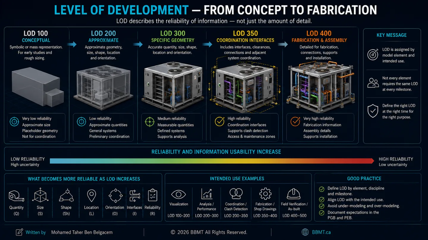
LOD 100 — Conceptual Representation
The element may be represented symbolically, graphically, or as part of a massing model.
It supports early studies but should not be relied on for precise size, shape, or location.
LOD 200 — Approximate Representation
The element is represented with approximate:
Quantity
Size
Shape
Location
Orientation
It can support preliminary coordination and analysis, but its geometry is not yet fully reliable.
LOD 300 — Specific Representation
The element’s quantity, size, shape, location, and orientation are modeled with sufficient specificity to support defined project uses.
The element can generally be measured directly from the model within the agreed modeling and accuracy rules.
LOD 350 — Coordination Interfaces
The element includes the interfaces or relationships required for coordination with adjacent or dependent elements.
Depending on the model element, this may include:
Supports
Openings
Connections
Required access zones
Major clearances
Interfaces with nearby systems
LOD 350 is often valuable for spatial coordination because it helps the team evaluate not only the object itself but also how it interacts with surrounding construction.
It should not automatically be required for every element. The required LOD must reflect the BIM use.
LOD 400 — Fabrication and Assembly
The element contains sufficient information for fabrication, assembly, or installation according to the defined scope.
This may include manufacturer-specific geometry, connections, supports, fabrication components, and assembly information.
Field-Verified Information
Some contracts use the term LOD 500 for field-verified or record conditions.
This should be used carefully.
A model should not be considered accurate simply because it has been labelled LOD 500. The agreement must also define:
What was verified
How it was verified
Who verified it
When it was verified
Required measurement accuracy
Accepted tolerances
Whether hidden conditions were verified
Which information is based on records rather than field measurement
A Model Does Not Have One LOD
The phrase “the model shall be LOD 300” is usually too vague.
Within one model:
Structural framing may be LOD 350.
Interior partitions may be LOD 300.
Mechanical equipment may be LOD 200.
Major ductwork may be LOD 350.
Furniture may remain LOD 100.
Fabricated systems may reach LOD 400.
LOD should therefore be assigned by:
Model element
Discipline
Project phase
Milestone
Responsible author
Intended use
The LOD Responsibility Matrix
A project LOD matrix should identify:
Model elementResponsible teamMilestoneRequired LODIntended useStructural beamsStructuralCoordination milestoneLOD 350Clash detection and openingsMajor ductworkMechanicalCoordination milestoneLOD 350Routing and clearance reviewMechanical equipmentMechanicalDesign milestoneLOD 300Space planning and coordinationInterior finishesArchitectureDesign milestoneLOD 300Documentation and quantitiesFabricated pipingTrade contractorConstructionLOD 400Fabrication and installation
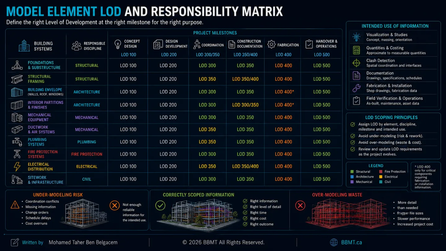
The matrix prevents two opposite failures:
Under-Modeling
The model does not contain enough reliable information for the intended use.
Over-Modeling
The team spends time creating information that is not required, will not be used, or is likely to change.
Both failures create cost and risk.
LOD and Level of Information Need
LOD should not be used as the only method for defining BIM deliverables.
Model information also includes:
Alphanumeric properties
Classifications
Documents
Certificates
Product data
Asset identifiers
Maintenance information
Inspection records
ISO 7817-1:2024 establishes principles for defining the Level of Information Need so information requirements can be specified consistently throughout an asset’s life cycle.
A robust requirement should therefore define:
Why the information is needed
Who will use it
When it must be delivered
Required geometry
Required alphanumeric information
Required documentation
Required accuracy
Required verification method
LOD communicates model-element reliability, but it does not replace a complete information requirement.
4. The Model Integrity Gate
The three pillars must be checked together before a model is accepted for coordination.
A geometrically detailed model can still fail if it uses incorrect coordinates.
A correctly georeferenced model can still fail if its elements are assigned to generic IFC classes.
A perfectly classified IFC can still fail if its geometry is too preliminary for clash detection.
The project team should therefore establish a model-integrity gate before every major exchange.
Exchange Configuration
Confirm:
Approved IFC schema
Approved exchange view or MVD
Export configuration
Receiving applications
File-naming requirements
Required model scope
Spatial Integrity
Confirm:
Correct project origin
Correct coordinate reference
Correct orientation
Correct elevation
Correct units
Correct site, building, storey, and space assignment
Classification Integrity
Confirm:
Correct IFC entities
Correct predefined types
Correct system assignment
Correct classifications
Limited use of generic proxy objects
A proxy is not automatically an error, but it should only be used when a more appropriate IFC entity does not exist or cannot be exported reliably.
Information Integrity
Confirm:
Required property sets
Required quantities
Required asset identifiers
Required classifications
Correct units
No duplicated or contradictory values
Compliance with IDS requirements where applicable
Geometric Integrity
Confirm:
No unintended duplicates
No corrupt geometry
No excessive detail
No missing elements
Appropriate openings and voids
Required clearances
Appropriate geometry for the intended use
Identity and Revision Integrity
Confirm:
Stable object identifiers where required
Correct model revision
Correct issue status
Traceable export date
Clear source-model ownership
Archived validation results
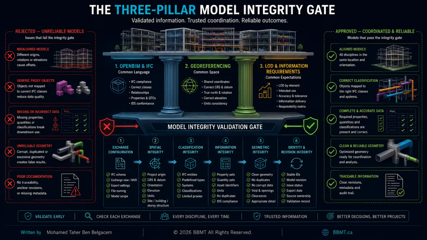
The objective is not to produce the largest or most detailed IFC file.
The objective is to produce the smallest reliable exchange that contains the correct information for its intended purpose.
Conclusion: The Infrastructure of Trust
BIM coordination is built on trust.
The mechanical team must trust that the structural beam is positioned correctly.
The structural team must trust that the mechanical route represents an agreed design rather than a temporary placeholder.
The coordinator must trust that the IFC model contains the correct objects, properties, relationships, and spatial structure.
The construction team must trust that the information being used for decisions is sufficiently developed and has passed the required validation.
That trust cannot be created by attractive three-dimensional graphics alone.
It is created through:
Open, testable information exchanges
Consistent IFC structures
Clearly defined information requirements
Verified coordinate systems
Element-specific LOD expectations
Controlled validation procedures
Transparent responsibility
openBIM provides the common language.
Georeferencing provides the common space.
Level of Development and information requirements provide the common expectations.
When all three pillars are properly implemented, the federated model becomes more than a visual coordination tool.
It becomes a reliable, traceable, and purpose-driven digital representation of the project.