

AEC Insights
The DNA of OpenBIM
openBIM is not simply about exporting models to IFC. This guide explores the standards, data structures, exchange rules, validation methods, and issue-management workflows that allow different BIM platforms to communicate without losing the meaning, ownership, or reliability of project information.

The DNA of openBIM
How IFC, IDS, BCF, and Open Standards Keep BIM Information Connected
Modern construction projects rarely operate within a single software environment.
Architects may design in Archicad. Structural engineers may work in Tekla Structures. Mechanical, electrical, and plumbing teams may use Revit or specialized analysis and fabrication applications. Contractors, coordinators, manufacturers, owners, and facility managers may depend on entirely different platforms.
Each participant contributes information to the same physical project, yet every application stores and organizes that information differently.
When collaboration depends exclusively on proprietary native files, project teams can encounter:
Software-version incompatibilities
Restricted access to information
Difficult or inconsistent file conversions
Loss of object classifications and properties
Unclear exchange responsibilities
Dependence on a particular software vendor
Long-term accessibility problems
Models that appear correct visually but behave incorrectly when analysed
The industry addresses this challenge through openBIM.
openBIM is a vendor-neutral approach to creating, exchanging, validating, and managing information across different platforms and throughout the lifecycle of a built asset. It does not require every participant to use identical software. Instead, it creates a common framework through which independently developed information can be understood and coordinated.
However, interoperability is not achieved simply by clicking Export.
A reliable exchange depends on a connected system of standards and processes:
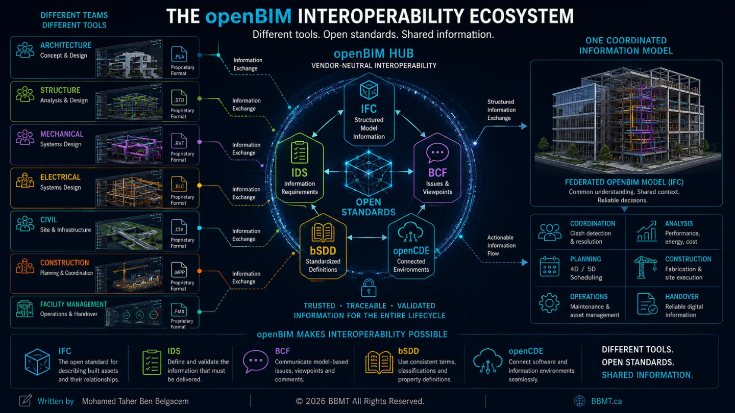
IFC structures and transports model information.
MVDs establish implementation rules for defined exchange workflows.
IDS states what information must be delivered.
bSDD provides standardized definitions.
BCF communicates model-based issues.
openCDE interfaces connect information-management platforms.
Validation confirms whether the information is usable.
Together, these components form the DNA of openBIM.
1. openBIM: Collaboration Without Software Lock-In
openBIM is not a particular application, model viewer, cloud platform, or file extension.
It is a collaborative methodology based on open standards and transparent information exchanges.
Its purpose is to allow project participants to select tools appropriate to their work while preserving the ability to exchange information with the wider project team.
buildingSMART’s openBIM ecosystem includes standards and services such as IFC, BCF, IDS, bSDD, openCDE interfaces, and validation services. These components support information exchange across project participants, applications, and asset-lifecycle stages.
The Universal-Adapter Metaphor
Interoperability can be compared to an international electrical adapter.
Different countries use different plugs and socket configurations. An adapter does not make those electrical systems identical. It creates a controlled interface that allows them to connect.
openBIM performs a similar function.
It does not convert every software platform into the same application. It provides open structures and communication methods that allow different platforms to exchange agreed information.
The objective is not identical software.
The objective is shared understanding.
The Core Components
IFC — Structured Model Information
Industry Foundation Classes provides an open and standardized method for describing built-asset information.
It can represent:
Projects and facilities
Sites, buildings, storeys, spaces, and zones
Physical elements
Geometry and placement
Materials
Properties and quantities
Classifications
Systems and connections
Relationships between objects
Actors, processes, and controls
IDS — Information Requirements
Information Delivery Specification allows information requirements to be expressed in a machine-interpretable form.
An IDS can define which:
IFC classes are permitted or required
Classifications must be assigned
Properties must exist
Values must follow specific rules
Materials or identifiers must be provided
The delivered IFC model can then be checked automatically against those requirements.
BCF — Issue Communication
BIM Collaboration Format communicates model-based issues without requiring the entire model to be resent each time.
A BCF issue can contain:
A title and description
Status and priority
Assigned responsibility
Comments
A snapshot
A saved viewpoint
Camera position
Referenced model elements
IFC GUIDs
Due dates and labels
bSDD — Standardized Definitions
The buildingSMART Data Dictionary helps project teams reference consistent terms, definitions, classifications, properties, and units.
This reduces the risk of different participants using different names for the same concept or the same name for different concepts. bSDD definitions can be referenced from both IFC and IDS workflows.
openCDE — Connected Information Environments
openCDE interfaces support software-to-software communication between connected information environments, document-management services, and issue-management platforms.
These standards are complementary:
IFC carries the information.
IDS defines the requirements.
bSDD standardizes the language.
BCF carries the coordination conversation.
openCDE connects the environments managing the information.
2. IFC: The Information Genome of the Built Asset
The backbone of model-based openBIM exchange is IFC, or Industry Foundation Classes.
IFC is sometimes described as the “PDF of BIM.” The comparison is useful because an IFC model can be accessed independently from the software in which it was authored.
However, IFC is much more than a visual publication format.
It is an open information schema that describes what model objects are, where they are located, how they are represented, what properties they contain, and how they relate to other objects.
The current international edition is ISO 16739-1:2024. It defines an open international standard for BIM information shared between construction and facility-management applications. Its scope includes buildings and infrastructure such as bridges, roads, railways, waterways, and port facilities.
IFC Is Not Automatically Reliable
An .ifc extension does not guarantee a high-quality exchange.
The usefulness of an IFC model depends on:
The quality of the source model
The selected IFC schema
The chosen exchange definition
Object-class mapping
Property and quantity configuration
Georeferencing
Geometry conversion
Model scope
Exporter behaviour
Receiving-software implementation
Post-export validation
An IFC model may open successfully while still containing:
Incorrect classes
Missing properties
Generic proxy objects
Wrong storey assignments
Incorrect coordinates
Duplicate elements
Oversimplified geometry
Excessive detail
Broken relationships
The exported file must therefore be inspected and validated independently.
IFC Is Not Inherently Non-Editable
Compatible applications can technically edit, transform, merge, or regenerate IFC information.
However, most multidisciplinary coordination workflows use IFC as a reference exchange.
In this type of workflow:
The originating discipline owns and maintains the source model.
The team publishes an IFC for coordination.
Other participants review that IFC as reference information.
Issues are communicated to the originating team.
Corrections are made in the responsible source model.
A revised IFC is exported and validated.
IFC4 Reference View is designed primarily for this type of reference-model exchange rather than unrestricted round-trip editing.
The professional rule is therefore:
Correct the source model. Re-export the IFC. Revalidate the exchange.
3. Inside an IFC Model
An IFC model is not simply a collection of three-dimensional shapes.
It is a network of objects, attributes, relationships, and spatial containers.
A useful metaphor is a highly organized filing cabinet.
The Cabinet: The Project
The cabinet represents the overall project or facility.
The Drawers: Spatial Organization
The drawers represent locations such as:
Site
Building
Storey
Space
Zone
Facility part
The Folders: Physical and Functional Objects
The folders represent:
Walls
Slabs
Beams
Columns
Doors
Ducts
Pipes
Equipment
Electrical systems
Assemblies
The Documents: Information Attached to Objects
The documents contain information such as:
Material
Dimensions
Manufacturer
Fire rating
Flow rate
Classification
Asset identifier
Quantity
System assignment
Maintenance information
The Anatomy of an IFC Object
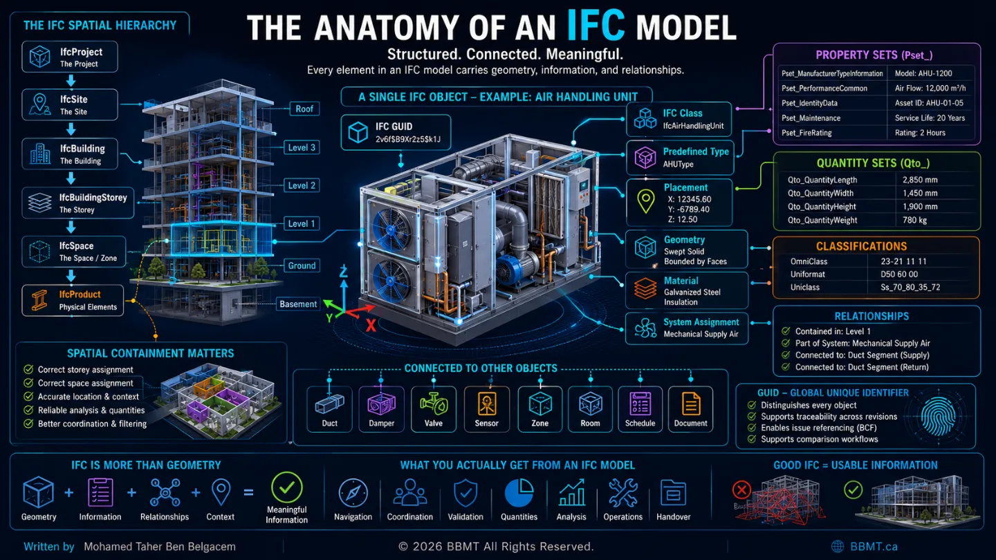
A properly structured IFC element may contain several layers of meaning.
Global Unique Identifier
Most IFC objects carry an IFC GUID—a globally unique identifier used to distinguish one object from another.
Stable identifiers can help coordination and comparison applications recognize corresponding objects between revisions.
However, GUID stability depends on how the source application and export workflow manage object identity.
IFC Class
The IFC class describes what the object represents.
Examples include:
IfcWall
IfcSlab
IfcBeam
IfcColumn
IfcDoor
IfcPipeSegment
IfcDuctSegment
IfcAirHandlingUnit
The receiving application may use the IFC class to:
Filter objects
Generate schedules
Run validation rules
Create quantities
Build clash tests
Assign systems
Locate assets
Incorrect classes can make otherwise valid geometry difficult to find or interpret.
Predefined Type
A predefined type further refines the meaning of an object within its class.
For example, an IfcCovering may represent flooring, ceiling, cladding, or another covering type.
Placement
Placement describes the position and orientation of an object.
The final location may depend on a chain of placements associated with:
The object
Its storey
The building
The site
The coordinate reference system
Geometry
IFC supports multiple geometry representations, including:
Extrusions
Swept solids
Tessellations
Boundary representations
Mapped geometry
Surface models
Boolean operations
The selected representation affects:
Precision
File size
Viewing performance
Receiving-software compatibility
Ability to calculate quantities
Materials
Materials may be assigned as:
Individual materials
Layer sets
Profile sets
Constituent sets
Material lists
Property Sets
Standardized IFC property-set names generally begin with Pset_.
Property sets may contain information related to:
Fire performance
Acoustic performance
Manufacturer data
Mechanical performance
Asset information
Operational requirements
Quantity Sets
Standard quantity-set names generally begin with Qto_.
They may contain:
Length
Area
Volume
Weight
Count
Height
Width
Perimeter
Classifications
Objects can reference classification systems such as:
Uniformat
OmniClass
Uniclass
MasterFormat
National classifications
Company-specific systems
Relationships
Relationships give IFC much of its intelligence.
An object can be related to:
A spatial container
A system
A material
A type
A classification
A property set
An assembly
Another connected object
A document
A process
An IFC model therefore explains not only what an object looks like, but also:
What it is
Where it belongs
What it contains
What system it serves
What information describes it
How it connects to the rest of the asset
4. The IFC Spatial Structure
A typical building IFC model may use a hierarchy such as:
IfcProject
↓
IfcSite
↓
IfcBuilding
↓
IfcBuildingStorey
↓
IfcSpace
Physical elements are then assigned to appropriate spatial containers.
This sequence is useful for understanding the structure, but it should not be interpreted as an unchangeable path through which every object must pass.
Depending on the project, some spatial levels may be optional. Elements are often contained directly by a building storey, while others may be associated with spaces, zones, facilities, or infrastructure-specific spatial structures.
Why Spatial Containment Matters
Correct spatial containment supports:
Storey-based filtering
Space-based analysis
Model navigation
Quantity extraction
Coordination reporting
Asset location
Facility-management workflows
Automated validation
Incorrect containment may cause an element to:
Appear under the wrong storey
Be omitted from floor-based filters
Lose its room context
Produce incorrect schedules
Be excluded from checking rules
Become difficult to locate after handover
A model may therefore appear geometrically aligned while remaining informationally incorrect.
5. Choosing the Right IFC Exchange
There is no single IFC configuration that is automatically correct for every project.
The selection depends on:
Intended use
Required information
Building or infrastructure scope
Geometry requirements
Receiving applications
Certified software capabilities
Owner requirements
Validation procedures
IFC2x3 Coordination View 2.0
IFC2x3 remains common in established building-coordination workflows.
Its strengths include:
Broad support in mature applications
Familiar workflows
Compatibility with legacy project environments
Stable implementation in many authoring and coordination tools
Its limitations include:
An older information schema
More limited infrastructure support
Fewer newer IFC concepts
Less flexibility than later schemas in some workflows
IFC4 Reference View
IFC4 Reference View is intended for reference-model exchanges, including:
Multidisciplinary coordination
Visual review
Clash detection
Model comparison
Quantity extraction
Construction planning
It should normally be treated as a published reference rather than a replacement for the original authoring model.
IFC4 Design Transfer View
Design Transfer View aims to carry more editable design information.
However, teams should not assume that an imported IFC will recreate the original parametric authoring model perfectly.
Round-trip behaviour depends heavily on:
The object types involved
Geometry representations
Software implementations
Parameter structures
Receiving-tool limitations
IFC 4.3
IFC 4.3 expands IFC into infrastructure and linear assets, including:
Roads
Railways
Bridges
Ports
Waterways
Alignments
Geographic positioning
The current ISO edition incorporates this expanded building-and-infrastructure scope.

The Test-Exchange Rule
The project team should not choose an IFC configuration solely because it is newer or more familiar.
A reliable selection process is:
Define the intended use.
Identify the receiving applications.
Define the required objects and information.
Select a proposed IFC schema and exchange definition.
Create a representative test model.
Export the test file.
Open it in every critical receiving application.
Check classes, properties, geometry, quantities, systems, and coordinates.
Document the approved configuration.
Apply the controlled configuration to future exchanges.
The correct IFC configuration is the one that reliably delivers the required information across the project’s actual software environment.
6. MVD and IDS: Structure the Exchange, Define the Requirements
The full IFC schema contains far more concepts than any individual exchange needs.
A coordination model, energy-analysis model, fabrication model, and asset-handover model do not require identical information.
Model View Definitions
A Model View Definition, or MVD, establishes implementation rules for a defined IFC exchange workflow.
It is often illustrated as a filter selecting part of the complete IFC schema. This is a helpful metaphor, but an MVD does more than remove unnecessary information.
It can define:
Which IFC entities are permitted
Which concepts must be implemented
Which relationships must be present
Which geometry representations may be used
How objects should be structured
Which constraints apply to the exchange
buildingSMART describes an MVD as a defined subset and implementation of the IFC schema for particular exchange needs. MVDs have also been used as a foundation for IFC software certification.
Information Delivery Specification
An Information Delivery Specification, or IDS, defines what information must be delivered in a machine-readable form.
For example, an IDS could require that every maintainable air-handling unit:
Uses the appropriate IFC class
Has a unique identifier
Includes a manufacturer
Includes a model number
Is assigned to a mechanical system
Is contained on a building storey
Includes specified performance properties
The delivered IFC can then be checked automatically.
MVD vs. IDS
The distinction can be summarized as:
MVD defines how an IFC exchange is implemented.
IDS defines what information the delivery must contain.

A controlled information-delivery process follows this sequence:
The receiving party defines the intended use.
Required information is identified.
Requirements are documented and, where appropriate, encoded in IDS.
The delivery team configures the authoring and export process.
An IFC is generated.
The IFC is validated against the requirements.
Noncompliant information is corrected.
The approved IFC is formally issued.
This moves IFC exchange away from informal expectations and toward measurable compliance.
7. Translating an Authoring Model into IFC
IFC is vendor-neutral, but each authoring platform must translate its own internal structure into the IFC schema.
Using Revit as an example, the source model organizes information through:
Categories
Families
Types
Instances
Parameters
Levels
Phases
Worksets
Design options
IFC organizes information through:
Entities
Predefined types
Spatial relationships
Properties
Quantities
Systems
Materials
Classifications
Geometry representations
The export is therefore not a simple file conversion.
It is a translation between two information structures.
Autodesk’s current documentation confirms that Revit’s IFC export process supports category-to-class mapping, predefined-type assignment, custom export setups, user-defined property sets, and the IfcExportAs mechanism for supported IFC classes.
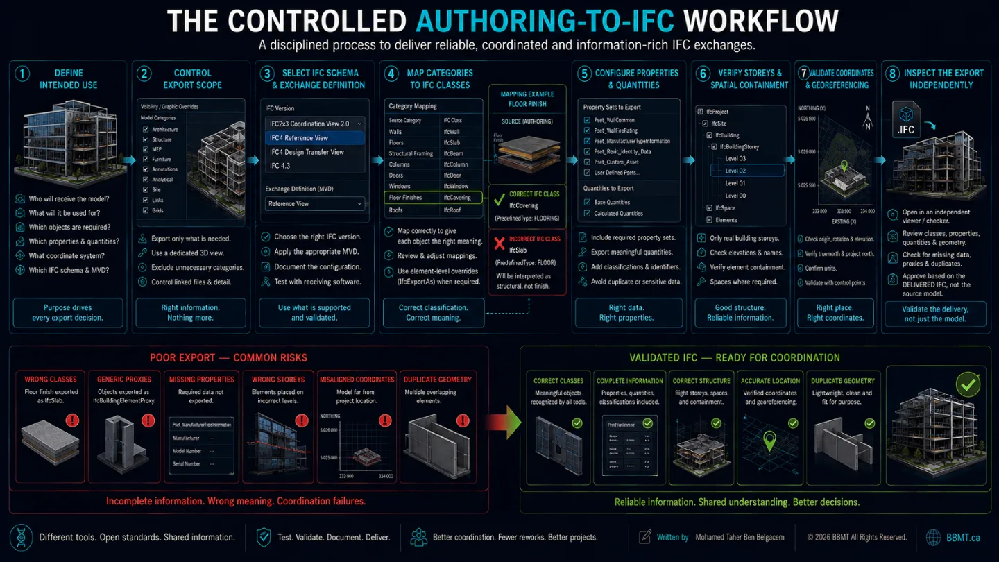
Rule 1: Define the Intended Use
Before opening the export settings, establish:
Who will receive the model
What they will use it for
Which objects they need
Which properties they require
Which coordinate system will govern the exchange
Which IFC configurations their tools support
Rule 2: Control the Export Scope
Only include information required for the exchange.
Possible controls include:
Exporting a designated 3D view
Excluding unnecessary categories
Separating buildings or disciplines
Removing temporary objects
Controlling linked models
Reducing excessive geometric detail
Too much information creates slow, heavy, and confusing files.
Too little information creates incomplete exchanges.
Rule 3: Map Categories to IFC Classes
Authoring-software categories do not always correspond directly to IFC classes.
The default mapping should be reviewed and adjusted where necessary.
Incorrect mapping can cause:
Structural elements to appear as generic proxies
Architectural finishes to be classified as slabs
Equipment to lose its functional meaning
Validation rules to fail
Quantities to be grouped incorrectly
Rule 4: Use Element-Level Overrides Carefully
When category-level mapping is insufficient, individual families or elements may require an IFC-class override.
In Revit, mechanisms such as IfcExportAs can be used for supported IFC-class assignment.
Overrides should be:
Standardized
Documented
Applied consistently
Reviewed after export
Included in the BIM Execution Plan
Rule 5: Control Properties and Quantities
The project team must decide whether to include:
Standard IFC property sets
Base quantities
Authoring-software properties
User-defined property sets
Classification data
Asset information
Schedule-based parameters
Exporting every available parameter can create duplicate, irrelevant, or sensitive information.
Exporting too little can leave the IFC geometrically complete but informationally useless.
Rule 6: Verify Storeys and Spatial Containment
Only real building storeys should normally become IfcBuildingStorey objects.
Reference levels used for ceilings, offsets, equipment, or temporary modelling should not automatically create unnecessary storeys.
After export, verify:
Storey names
Storey elevations
Element containment
Space placement
Building organization
Rule 7: Validate Coordinates
Confirm:
Origin
Easting
Northing
Elevation
Rotation
True north
Units
Site placement
Building placement
Use at least:
One known control point
A second point to verify rotation
A known elevation
Rule 8: Inspect the Delivered IFC Independently
The source model is not proof that the IFC is correct.
Open the IFC in a separate viewer or checking platform and inspect:
Object classes
Types
Storeys
Spaces
Systems
Properties
Quantities
Geometry
Coordinates
Missing elements
Duplicate objects
Generic proxies
8. BCF: The Communication Layer of openBIM
IFC carries the model information.
But when a coordinator discovers a problem, sending another complete model is not the most efficient way to communicate it.
Historically, coordination teams relied on:
Email
Screenshots
PDF reports
Spreadsheets
Meeting minutes
Written coordinates
These methods quickly became disconnected from the models they described.
BIM Collaboration Format, or BCF, provides a structured and software-independent method for communicating model-based issues.
buildingSMART describes BCF as an open standard for communicating model issues through files or web-based services. BCF can carry viewpoints, snapshots, comments, and references to IFC model elements.
IFC Carries the Model; BCF Carries the Conversation
A BCF issue may contain:
Title
Description
Status
Priority
Responsible person or team
Due date
Snapshot
Saved camera position
Clipping planes
Selected objects
IFC GUID references
Comments
Labels
Building level or zone
In compatible applications, opening the issue may:
Restore the saved viewpoint
Select the relevant elements
Display the issue snapshot
Show comments and metadata
Navigate directly to the coordination context
The exact behaviour depends on the receiving application and its BCF implementation.
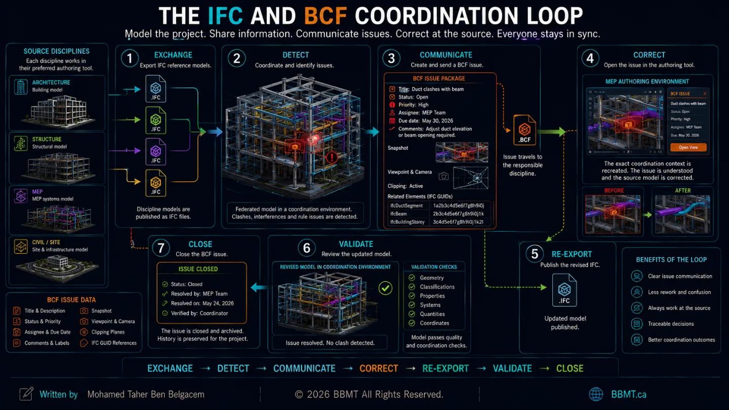
The IFC–BCF Coordination Loop
A typical workflow is:
Discipline teams export IFC reference models.
The models are federated.
The coordinator identifies an issue.
The issue is documented in BCF.
The BCF issue is assigned to the responsible team.
The modeler opens the issue in a compatible authoring application.
The source model is corrected.
A revised IFC is exported.
The coordinator validates the correction.
The BCF issue is resolved and closed.
BCF prevents model-based communication from becoming trapped in static reports or a single software platform.
9. The IFC Quality Gate
Before a formal IFC exchange is accepted, it should pass a structured quality review.
Exchange Definition
Confirm:
Approved IFC schema
Approved MVD or exchange definition
Defined intended use
Identified receiving applications
Completed test exchange
File Control
Confirm:
Correct file name
Correct project
Correct discipline
Correct revision
Correct issue date
Correct model scope
Spatial Structure
Confirm:
Valid project structure
Correct building
Correct storeys
Required spaces
Appropriate element containment
Positioning
Confirm:
Correct coordinate system
Correct origin
Correct elevation
Correct rotation
Correct units
Verified control points
Classification
Confirm:
Appropriate IFC classes
Correct predefined types
Correct classifications
Correct system assignments
Limited and justified proxy use
Information
Confirm:
Required properties
Required quantities
Correct units
Required identifiers
No contradictory values
IDS compliance where required
Geometry
Confirm:
Required elements are present
No unintended duplicates
No visibly corrupt geometry
Correct openings
Appropriate detail
Reasonable file size
Identity and Revision
Confirm:
Stable identifiers where required
Traceable source ownership
Correct revision
Archived validation results
Clear issue status
The objective is not to create the largest or most detailed IFC file.
The objective is to create:
The smallest reliable exchange containing the correct information for its intended purpose.
Conclusion: Interoperability Is a Managed Agreement
openBIM does not eliminate the need for discipline.
It makes discipline measurable.
IFC cannot repair an incomplete source model.
An MVD cannot decide what the client needs.
IDS cannot validate information that was never created.
BCF cannot resolve an issue that no one accepts responsibility for.
Interoperability succeeds when the project team agrees on:
Exchange purposes
Information requirements
IFC schemas
Model View Definitions
Classification rules
Coordinate systems
Export settings
Validation methods
Issue workflows
Model ownership
Correction responsibilities
openBIM provides the ecosystem.
IFC carries the structured model information.
MVDs define how supported exchanges are implemented.
IDS defines the information that must be delivered.
bSDD creates a shared vocabulary.
BCF communicates what must be resolved.
When these components work together, information can move between software platforms without becoming disconnected from its purpose, meaning, or ownership.
That is the DNA of openBIM:
Different tools. Open standards. Shared information.