

BIM Coordination
The Mechanics of BIM Coordination
Coordination Cycles, Clash Detection, and Issue Resolution. BIM coordination is more than running clash-detection software. This chapter explains how teams use structured coordination cycles, model-readiness checks, priority-based clash testing, and connected issue tracking to turn separate discipline models into one coordinated and constructible project.
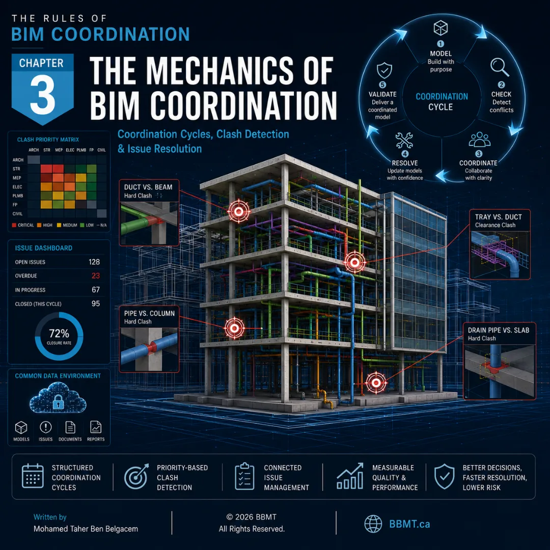
Chapter 3: The Mechanics of BIM Coordination
Coordination Cycles, Clash Detection, and Issue Resolution
In the previous chapter, we established the governance framework of a BIM project through the Project BIM Management Plan and BIM Execution Plans.
Once those documents are approved, however, the real coordination work begins.
Separate architectural, structural, mechanical, electrical, plumbing, civil, fabrication, and construction models must be reviewed together and transformed into one coordinated digital representation of the project.
How are the models collected and validated? Which systems should be tested first? How are irrelevant clashes filtered out? Who is responsible for each conflict? How is an issue tracked from its initial detection to its final closure?
The answer lies in a disciplined coordination process built around three connected mechanisms:
A repeatable coordination cycle
Structured clash detection and model review
Collaborative issue assignment, resolution, and validation
Three-dimensional coordination is one of the most valuable BIM applications because it allows project teams to identify geometric and spatial conflicts before those conflicts reach the construction site.
However, clash detection alone does not create a coordinated project.
Software can identify intersections. Only the project team can evaluate them, agree on solutions, modify the models, and confirm that the conflicts have been resolved.
1. The Coordination Cycle: A Repeatable Project Rhythm
BIM coordination is not a one-time event performed immediately before construction.
It is an iterative cycle of model production, internal review, information exchange, clash analysis, decision-making, correction, and validation.
A successful project requires a predictable coordination rhythm so every participant understands:
When models must be ready
When internal reviews must occur
When information must be shared
When coordination tests will be performed
When meetings will take place
When corrections are due
When issues will be validated and closed
The exact schedule should be established in the Project BIM Management Plan and reflected in each team’s BIM Execution Plan.
The following 11-working-day countdown is one example of a structured coordination cycle before a major project milestone.
Step 1 — Day −11: Internal Discipline Quality Control
Each discipline performs its own internal review before sharing information with the wider project team.
The team confirms that its model is sufficiently complete, correctly positioned, properly classified, and suitable for interdisciplinary review.
The internal review may include:
Model-health checks
Coordinate verification
Duplicate-element detection
Warning and error reviews
Naming-convention checks
Required-parameter checks
Model completeness reviews
Visual inspection
Export testing
Only models that pass the internal review should be uploaded to the Common Data Environment.
Step 2 — Day −10: Model Federation and Clash Analysis
The BIM coordinator collects the approved discipline models and loads them into the federated coordination environment.
Before running tests, the coordinator verifies:
File versions
Model origins
Shared coordinates
Units
Levels and grids
Model orientation
File names
Required discipline content
The coordinator then performs visual reviews and runs the agreed clash tests.
Step 3 — Day −9: Clash Filtering and Issue Publication
Automated tests may identify hundreds or thousands of intersections.
The coordinator reviews the results and removes:
Duplicate results
Approved penetrations
Intentional connections
Self-intersections
Minor or irrelevant contacts
Conflicts already covered by another issue
Results below the project’s reporting threshold
Valid coordination problems are converted into assigned issues.
Each issue should include:
A clear title
A visual viewpoint
The affected models or systems
The building, level, and zone
The responsible team
Priority or severity
Required action
Due date
Supporting comments or references
Step 4 — Day −8: Interdisciplinary Coordination Meeting
The project team reviews significant or unresolved issues using the federated model as a shared decision-making environment.
The purpose of the meeting is not to read every clash one by one.
The meeting should focus on issues that require:
Input from multiple disciplines
A design decision
A change in system routing
A structural or architectural modification
Owner approval
Construction sequencing input
Fabrication or installation expertise
Each issue should leave the meeting with a defined decision, responsible party, and deadline.
Steps 5 and 6 — Days −7 to −2: Model Corrections
The responsible model authors correct the identified conflicts in their native authoring platforms.
A modeler should not move an element simply to remove a clash symbol.
The correction must maintain:
Design intent
Code compliance
Required clearances
System performance
Constructability
Maintenance access
Fabrication requirements
Architectural quality
Structural integrity
Updated models are internally reviewed and shared again through the Common Data Environment.
Step 7 — Day −2: Resolution Validation
The BIM coordinator reloads the revised models and confirms that the assigned issues have been resolved.
Issues should only be closed when the corrected geometry or information is visible in the approved model.
A verbal confirmation or meeting note is not sufficient evidence of closure.
Step 8 — Day +1: Persistent-Issue Review and Process Improvement
After the milestone, the project team reviews any persistent or unresolved issues.
This review may identify:
Issues requiring owner decisions
Conflicts delayed by incomplete design
Repeated coordination failures
Inadequate modeling standards
Missing information
Unrealistic deadlines
Problems in the current exchange workflow
The objective is not only to resolve remaining conflicts. It is also to improve the next coordination cycle.
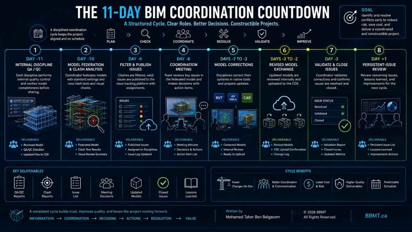
A structured cycle creates accountability. Every discipline knows when its model must be ready, when decisions must be made, and when corrections must be completed.
2. Internal QA/QC: Clean Your Own Model First
One of the most important rules of professional BIM coordination is simple:
Internal discipline coordination must occur before interdisciplinary coordination.
The architectural team should not rely on the project BIM coordinator to identify architectural modeling errors.
The structural team should not submit overlapping beams, duplicated columns, or misaligned levels for the wider team to discover.
Mechanical, electrical, and plumbing teams should review their own systems for internal conflicts before testing them against architecture and structure.
When incomplete or poorly controlled models enter the coordination environment, the number of irrelevant clashes increases dramatically.
The result is wasted time, reduced confidence in the reports, and longer coordination meetings.
Typical Internal Model Checks
Before a model is shared, the discipline team should verify:
Model origin and coordinates
Grids and levels
Duplicate or overlapping elements
Disconnected system components
Orphaned objects
Objects placed on incorrect levels
Missing classifications
Incomplete required parameters
Incorrect object types
Excessive warnings
Imported or linked content
File size and model performance
Required clearances
Design completeness
Export quality
The Model Readiness Plan
A model should not be treated as either completely finished or completely unfinished.
Different systems and building zones may reach coordination readiness at different times.
A Model Readiness Plan helps the project team track the maturity of the information that will enter the coordination process.
The plan may list:
Grids and levels
Foundations
Structural framing
Building envelope
Interior partitions
Vertical circulation
Mechanical equipment
Ductwork
Plumbing systems
Fire-protection systems
Electrical distribution
Civil utilities
Landscape elements
Fabrication models
Each item can be assigned a clear status such as:
In Development
On Hold
Ready for Coordination
Validated
Frozen for Milestone
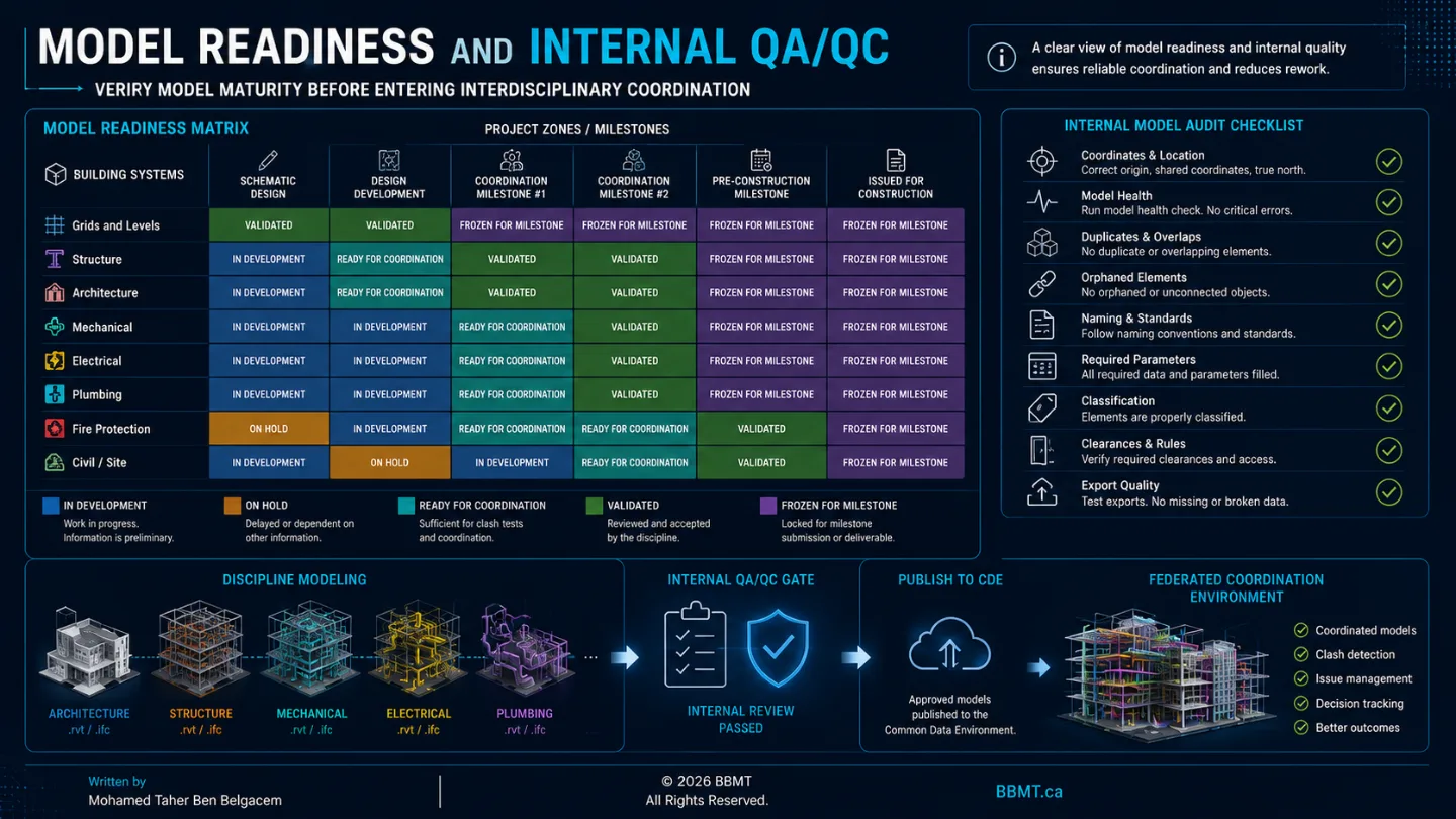
The purpose of the readiness plan is transparency.
The coordinator must know whether a model represents approved design information, preliminary routing, placeholder geometry, or incomplete work.
A clash involving two validated systems requires immediate action.
A clash involving a preliminary placeholder and an incomplete design may simply need to be monitored until more information is available.
3. The Clash Priority Matrix: Controlling the Signal-to-Noise Ratio
One of the most common mistakes in clash detection is running a single test between every element in every model.
This creates an overwhelming quantity of results.
Many of those results may be:
Intentional intersections
Low-priority finish conflicts
Duplicate clashes
Temporary design conditions
Minor tolerance contacts
Approved penetrations
Conflicts involving incomplete systems
Results that do not require a design change
When everything is tested against everything, critical issues become buried inside irrelevant data.
This is known as a poor signal-to-noise ratio.
Prioritize the Systems That Control Space
A clash priority matrix identifies which model categories should be tested against one another and in what order.
The matrix may consider:
System rigidity
Ability to reroute
Required clearances
Installation sequence
Cost of modification
Structural significance
Architectural impact
Fabrication status
Project risk
Decision authority
For example, a typical coordination sequence may begin with:
Structure vs. major mechanical systems
Structure vs. plumbing and fire protection
Structure vs. electrical containment
Major mechanical vs. plumbing
Major mechanical vs. electrical
Architecture vs. major building systems
Secondary systems and finish coordination
This sequence is not universal. It should reflect the project’s construction system, design maturity, and coordination priorities.
Which System Should Move?
The clash matrix may also help establish which discipline normally has the greatest flexibility to adjust.
However, responsibility should never be determined only by a fixed hierarchy.
The correct solution may depend on:
Required slope
Structural loading
Minimum clearance
Ceiling height
Maintenance access
Fire rating
Installation sequence
Equipment performance
Fabrication restrictions
Cost and schedule impact
A large gravity drainage pipe may have less flexibility than a small electrical conduit.
A primary structural beam will generally have less routing flexibility than a branch duct.
A prefabricated assembly may be more difficult to modify than a system that has not yet entered fabrication.
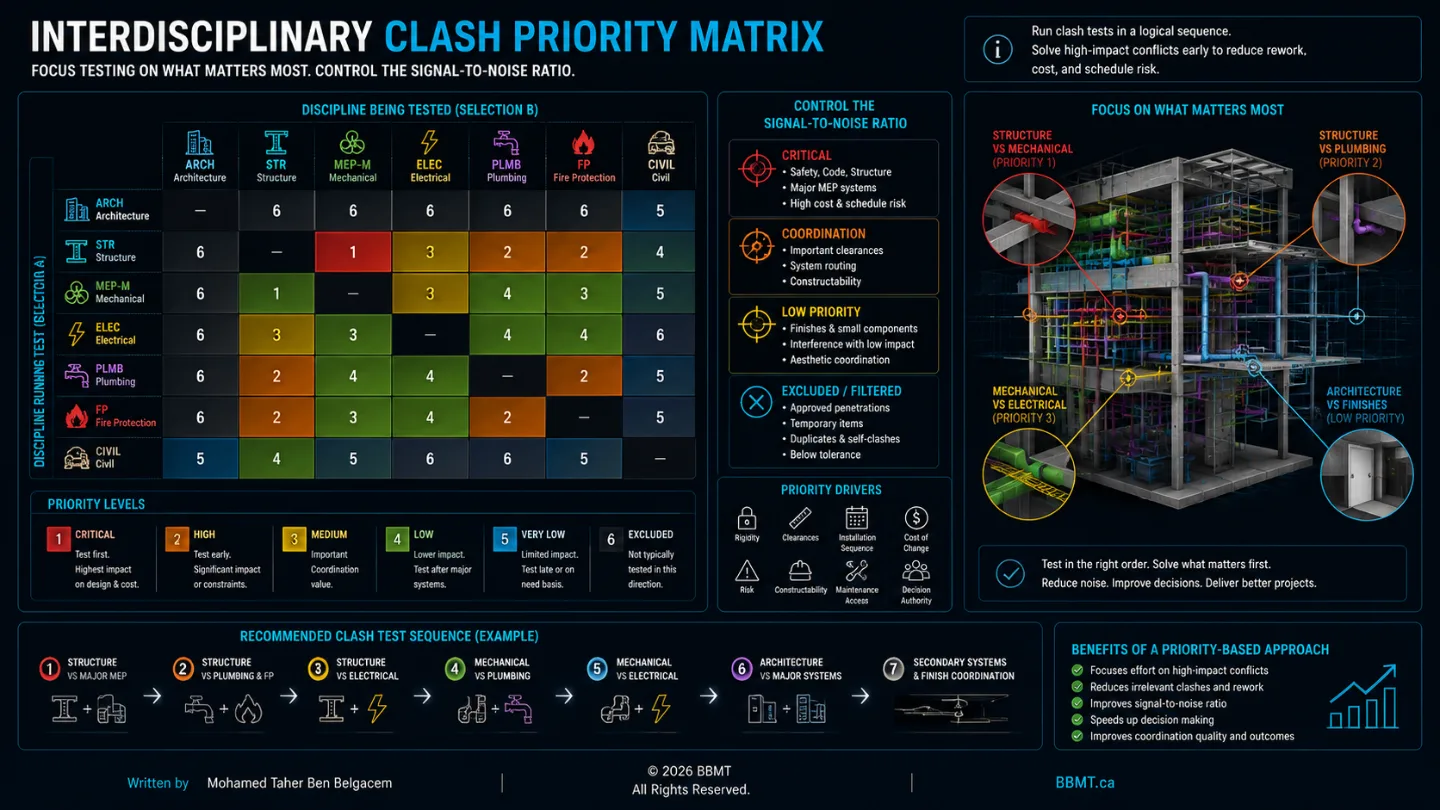
The priority matrix helps the coordinator run focused tests and direct attention toward the conflicts with the greatest project impact.
4. The Clash Engine: From Test Setup to Useful Results
Coordination platforms such as Autodesk Navisworks Manage, Solibri, Autodesk Construction Cloud Model Coordination, Revizto, and similar tools can automate geometric comparisons between models.
Although the interfaces differ, a disciplined clash-analysis process usually follows the same general sequence.
Step 1: Define the Test
Each test should have a clear and consistent name.
A useful naming structure may include:
Test number
Discipline A
Discipline B
Building or zone
Clash type
Revision date
For example:
CL-04 — Structure vs. Mechanical — Level 03 — Hard Clash
Clear test names make reports easier to understand and maintain.
Step 2: Define Rules and Exclusions
The coordinator establishes which conditions should be ignored.
Possible exclusions include:
Elements in the same approved assembly
Duplicate representations
Intentional penetrations
Linked reference geometry
Temporary construction objects
Elements below a defined size
Objects assigned to an excluded status
Previously approved exceptions
Exclusions should be documented. Hidden rules that only one coordinator understands create inconsistency and reduce trust in the results.
Step 3: Select Structured Model Sets
Tests should be based on organized selection sets rather than manually selected objects.
Examples include:
Structural beams
Structural columns
Concrete walls
Major supply ductwork
Sanitary drainage
Fire-protection mains
Electrical cable trays
Equipment clearance zones
Ceiling systems
Doors and circulation zones
Selection sets make tests repeatable when revised models are received.
Step 4: Define Clash Type and Tolerance
The coordinator determines what kind of conflict the test is intended to identify.
Common clash types include:
Hard Clash
Two physical objects occupy the same space.
Examples:
A duct passing through a beam
A pipe intersecting a concrete wall without an opening
Cable tray crossing structural bracing
Clearance Clash
An element violates a required access or maintenance zone.
Examples:
Equipment installed too close to a wall
Insufficient access in front of an electrical panel
Ductwork blocking a valve-maintenance zone
Workflow or Sequence Conflict
Two activities or installations cannot occur as planned because of timing, access, or construction sequence.
The project team should define tolerances according to the test purpose.
A tolerance appropriate for concrete structure may not be appropriate for finish coordination, fabrication, or maintenance-clearance analysis.
Step 5: Run, Review, and Group the Results
After the test is run, the coordinator reviews the clashes and groups related results.
A single design problem may generate several geometric clashes.
For example, one duct crossing a line of structural framing members may create multiple clash points. These should often be grouped into one coordination issue representing the underlying routing problem.
Grouping should be based on:
Common cause
Same system
Same location
Same required decision
Same responsible team
Same corrective action
Step 6: Convert Valid Results into Issues
A clash result becomes useful only when it is converted into an actionable issue.
The issue should explain:
What is wrong
Where it is located
Why it matters
Which team is responsible
What decision or correction is required
When the correction is due
Step 7: Report and Communicate
Reports may be exported in formats such as:
HTML
XML
PDF
Spreadsheet
BCF
Platform-native issue records
Static reports may still be useful for milestone records and formal submissions.
However, active coordination should preferably occur through a connected issue-management environment.
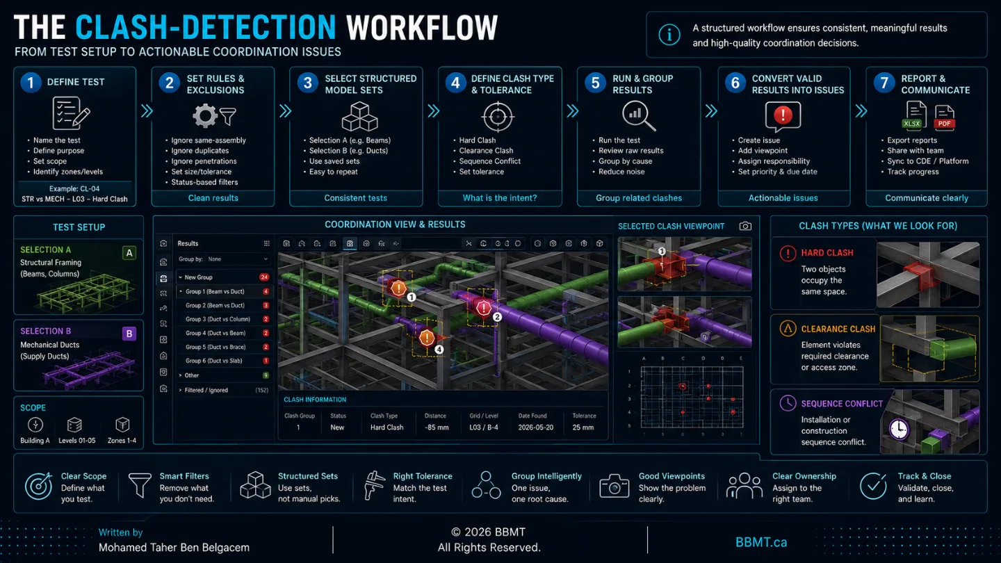
The quality of the clash results depends more on the test strategy than on the software.
A poorly structured test in advanced software will still produce poor coordination information.
5. From Static Clash Reports to Connected Issue Management
Historically, BIM coordination issues were documented through spreadsheets, screenshots, PDFs, and long email chains.
These methods create several problems:
Reports quickly become outdated
Issue ownership becomes unclear
Comments are distributed across different platforms
Modelers cannot easily locate the conflict
Closed issues may reappear
There is limited version history
Managers cannot reliably measure progress
Teams may work from different issue lists
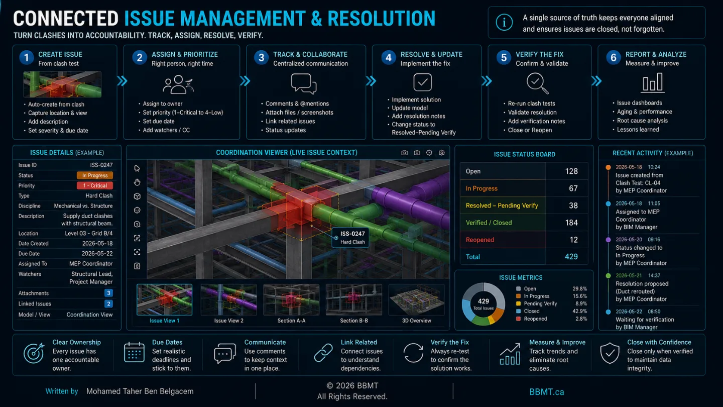
Modern coordination platforms convert each issue into a controlled digital record.
The Issue Lifecycle
A well-managed coordination issue may move through the following statuses:
Open — A valid issue has been identified
Assigned — A responsible team or person has been selected
In Progress — The team is evaluating or correcting the issue
Ready for Review — A revised model has been submitted
Resolved — The correction has been verified
Closed — The issue is formally completed
Reopened — The issue remains or has returned in a later model
Each issue should retain:
Creation date
Creator
Responsible team
Assigned person
Priority
Due date
Location
Model references
Viewpoint
Comments
Attachments
Status history
Resolution evidence
Direct Connection to Authoring Tools
Modern issue-management platforms may connect directly with authoring software.
A modeler can select an assigned issue and automatically open the relevant model view or location.
This reduces the time spent searching for:
The correct building
The correct floor
The correct room
The correct model elements
The exact clash coordinates
BCF-based workflows and platform integrations can transfer viewpoints, comments, selected elements, and issue metadata between coordination and authoring environments.
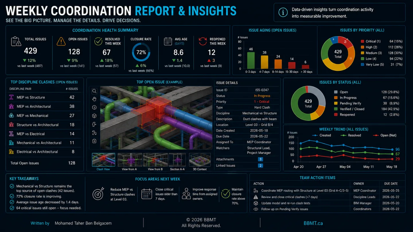
Live Coordination Analytics
Connected issue data allows project managers to monitor:
Open issues by discipline
Overdue issues
Average resolution time
High-risk zones
Repeated conflicts
Issue creation and closure rates
Milestone readiness
Model quality trends
The goal is not to create a dashboard for its own sake.
The goal is to identify coordination risk early enough for the project team to act.
6. The Coordination Meeting: From Clash Review to Decision-Making
A coordination meeting should not become a screen-sharing session in which the coordinator scrolls through hundreds of clashes.
The meeting must be structured around decisions.
Before the meeting, the coordinator should:
Filter the automated results
Group related clashes
Assign preliminary priorities
Identify the responsible disciplines
Separate simple issues from decision-level issues
Prepare clear viewpoints
Distribute the agenda
Confirm that the relevant decision-makers will attend
During the meeting, each issue should be reviewed by asking:
What is the actual design or construction problem?
Which requirements control the solution?
Which systems can realistically move?
Who has authority to approve the change?
What is the agreed corrective action?
Who is responsible?
When is the revised model due?
After the meeting, decisions must be recorded in the issue-management platform.
A successful coordination meeting produces fewer unresolved questions, not simply more screenshots and comments.
Conclusion: Coordination Is a Team Process
Clash-detection software identifies geometric conditions.
It does not determine the best design solution.
It does not understand contractual responsibility, construction sequence, maintenance access, structural integrity, architectural intent, or project cost unless the project team provides that context.
True BIM coordination is therefore a collaborative process.
Success depends on architects, engineers, contractors, fabricators, coordinators, and model authors agreeing to:
Share reliable information
Follow a repeatable coordination cycle
Review their own models before submission
Prioritize meaningful clashes
Assign clear responsibility
Make timely decisions
Correct issues in the source models
Validate corrections before closure
Learn from repeated coordination problems
When teams resolve geometric and spatial conflicts in the virtual environment, they reduce uncertainty before construction begins.
The result is not necessarily a model with zero detected intersections.
The real objective is a coordinated, constructible, maintainable, and clearly documented project in which the remaining risks are understood and accepted by the responsible participants.